| 1 |
|
8 hrs |
| 2 | 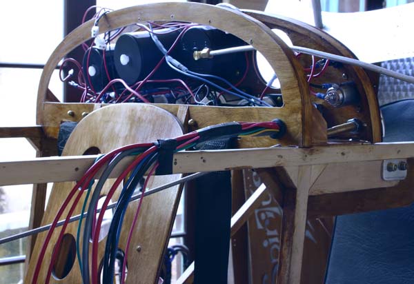 |
Kept
on working on wiring the panel. Got some yellow, blue, green and
pink wire to color code the different instruments. I ended up with
a pretty good wad of wire to run from the panel to the front of
the plane. I will tape them together as a harness with black electrician
tape. |
4 hrs |
| 4 |
|
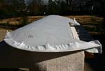
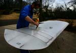
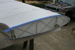
The weather was still beautiful and even warmer this morning, so I got an early start covering the other side of the first top wing. This is my third, and I am begining to feel I know what I am doing. So I will not impose the lesson to everybody, but for those of you up to it, I put together a detailed photo step by stw I do it. Keep in mind that this is only the best way I found to do it , and is not a replacement for the Polyfiber manual. You can follow the link below to see it: |
5 hrs |
Well, I got lazy these last few days and did not keep the daily logs too well. I got the last wing covered, and te engine installed. But I did shoot pictures, so here they are.
 |
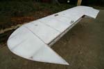
The fourth and last wing was covered, shrunk, and got its coat of Polybrush. |
12hrs |
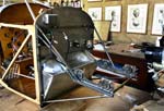 |
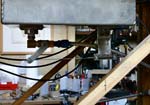
The engine mount was finally welded together, cleaned up, and bolted in place to the firewall. . |
4 hrs |
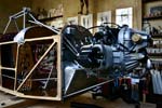 |
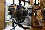
The mount was slipped in place under the engine by lifting the tail up and sliding the fuselage forward , and the engine was bolted to the mount . Some wood blocks were placed under the forward channel of the landing gear, and the wood blocks supporting the engine were removed . |
2 hrs |
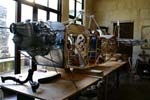 |
The fuselage was front heavy, and I had to place the battery all the way near the tail and add about 9 lbs to get it to balance on the gear channel.It seemed to me like I had a problem ,so I called Gene about this , and he said it was OK. |
2 hrs |
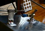 |
The bracket waswelded to the bottom of the gas tank, and I screwed on the valve . |
5 hrs |
 |
The gas gauge was mounted to the top. The tank was strapped in place with 2 one inch stainless steel strips in rubber channels. |
2hrs |
 |
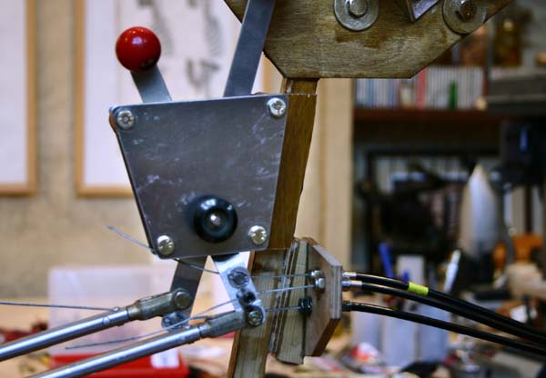
The remote valve control cable was connected. For safety reasons, so the gas is not turned off unintentionnaly, the valve is open when the T-handle control is pushed in , and closed by pulling it out. |
5 hrs |
 |
I found an electrical aluminum fitting that screwws on the gas filler neck, and fill cut it and grind it to fit my antique filler cap. |
1 hrs |
 |
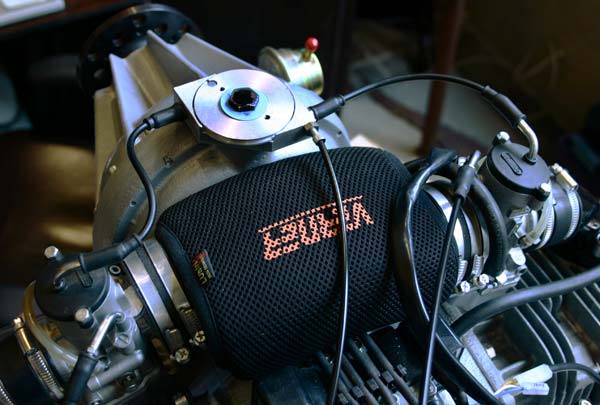
The exhaust manifolds and muffler were bolted on . There is a problem with the lower right bracket of the mount interfeering with the manifold, so I will have to cut it a little shorter and have it rewelded. The muffler is not centered , and there is nothing much I can do . |
2 hrs |
 |
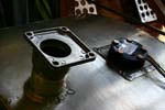
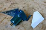
I made a cardboard pattern for the gascolator bracket, and cut it out of 1/8" aluminum. Drilled a hole to fit the gas intake, and bolted the gascolator on. |
2 hrs |
 |
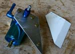
I cut a piece of angle aluminum and bolted it to it. |
1 hrs |
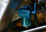 |
The gascolator was attached to the firewall, and fits vertically as planned. |
5 hrs |
 |
Got one of the wings out on the stands top side up to figure out the best spacing and location for the stitches so there is no interference with spars or the geodetic strips. It took trial and error , marking potential positions on masking tape , to arrive at a solution. |
2 hrs |
 |
There will be 17 stitches per rib, and the spacing will be 2 3/8"between the leading edge and the main spar, and 2 1/2 "" between the main spar and the trailing edge. That was the only way to work around the geodetic and the spars. I then drew vertical lines between the top and bottom of the root rib, , and markes the spacing for the bottom of the wing. Made another tape template for the top of the full ribs, and one for the bottom .
|
2 hrs |
 |
I do not want to strike a bunch of chalk lines on the fabric, since it will not be painted, so I am going to use the tape templates to mark each rib individually. |
1 hrs |
| N E X T M O N T H | L A S T M O N T H | I N D E X | B A C K T O I N T R O |