|
| C
O N S T R U C T I O N L O G |
|
| J
A N U A R Y 2 0 0 5 |
|
 |
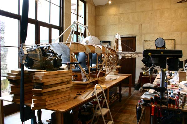
| Nothing
was done since December 3, better get going! 841 hours of labor so far... |
|
| 7 |
|
Cut
scallops in leading edge ply, and spackled with Aeropoxy. |
|
3
hrs |
|
|
| 11 |
 |
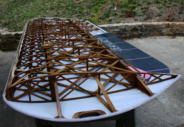
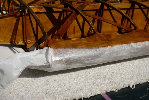
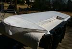
Brushed
2 coats of Poly-brush on leading edge, trailing edge , edged
or aileron bay , wing tip bow, and root rib.
Snapped two chalk lines 2" apart on each side of center of leading edge.
Held fabric in place with clamps and trimmed it at trailing edge and aileron
bay.
Glued
fabric along leading edge in a 2" strip of Poly-Tak. Glued
to trailing edge and aileron bay.
Ironed
fabric around the wing tips, trimmed it. Glued fabric to wing tip
bows. It was actually easier than I thought to pull it smooth. |
 |
In
order to get the Poly-Tak to soak through the fine weave light
weight fabric when it is pressed into it, I had to thin it
a little with MEK. I brushed about 18" of Poly-Tak at
a time and quickly pressed the fabric into it with the palm
of my hands. If necessary, I used the brush and a little more
glue to press it in.Turned the wing over . Ironed the fabric
over the trailing edge at 225 and glued it to the top
side.
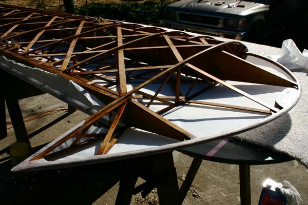
Covered
root rib with fabric and wrapped it around to the top 1" strip.
Trimmed extra fabric with razor blades. Installed aileron push
rod. |
 |
Sanded
edge of fabric lightly on leading edge, and brushed some Poly-Brush
on.
Glued
inspection rings for aileron bell crank, and to install aileron
hinge pin. |
|
|
6
hrs |
|
|
| 12 |
 |
Cut
and fit two 1/8"plywood plates with an elongated hole around
the rudder push/pull rods . Used spacers to make it level with
the bottom longeron.
|
|
3
hrs |
|
|
| 13 |
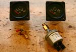 |
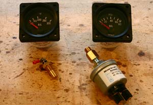
Received
my Mitchell oil pressure and oil temperature gauges from Aircraft
Spruce today , both with 1/8NTP sensor, as well as a 1/8NTP to
10/1 mm metric adapter that will fit the pressure sensor. I still
need to find a 1/8 NTP TO 10/1.5 mm adapter for the temperature
probe. |
 |
I
have exchanged e-mails with Westach about a dual 2 1/4" square
CHT gauge Model 2DA8( $103.30), and two 12mm spark plug thermocouples
type 710-8WK ($16.60 each), plus $8.40 per red arc marking .
Aircraft Spruce actually sells the same gauge for only . $79.25. That
would leave a slot open for the Mitchell Voltmeter.
The other option would be to use 2 single CHT gauges and no
voltmeter. |
 |
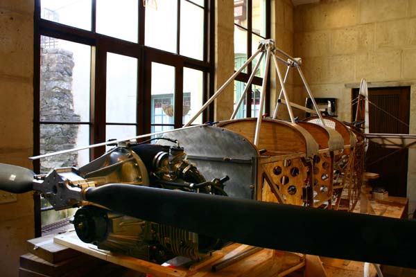
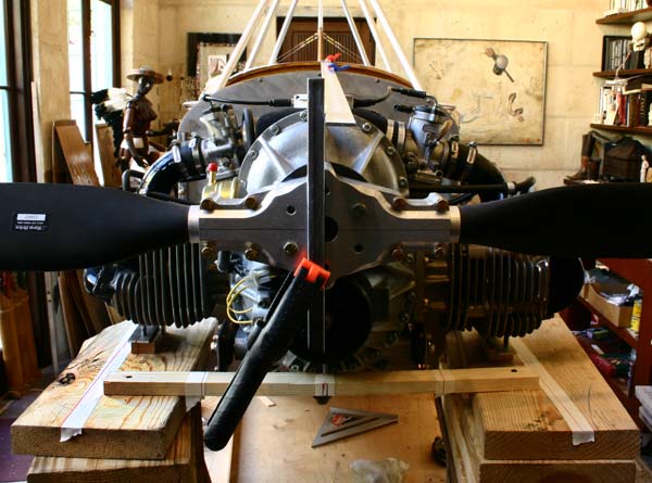
Also
received my 72" Warp Drive prop with its two skinny black
square tiped carbon fiber blades. It is not exactly ugly, but
I still long for an old fashion 2 color laminated wood prop with
wide rounded blades... |
 |
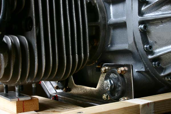
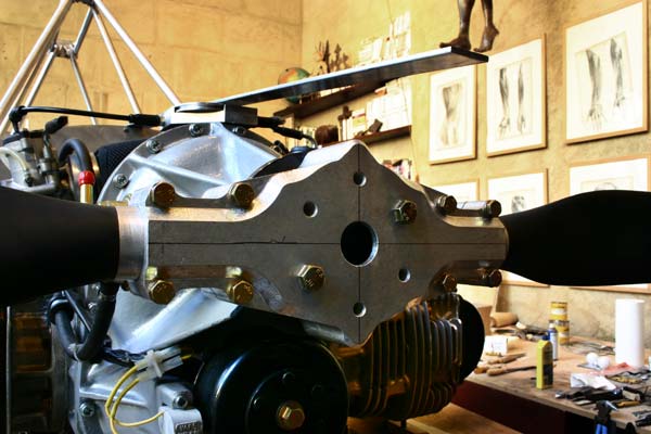
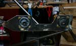
Finally
got my engine mounting plates back from the tin shop. Sanded
them shiny.
Attached the Lord mounts with AN3-4A bolts , and attached the assemblies
to the engine with 10 mm-1.5 x 50 mm metric X head bolts and washers. |
|
|
2
hrs |
|
|
|
|
| 17 |
 |
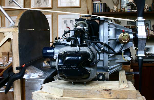
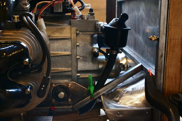
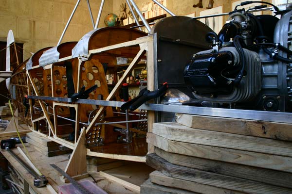
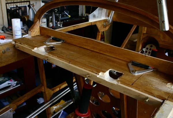
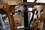
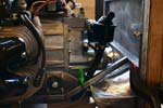
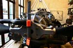
In
order to move the engine as close to the firewall as possible,
I had to cut a hole in the boot to make space for the oil outlet
to the cooler and the oil pressure sensor. The protrusion will
be covered with a metal cup. A 90 degree fitting at the oil outlet
toward the forward mounted oil cooler would help too and keep
the rubber hose from protruding between the pedals. |
 |
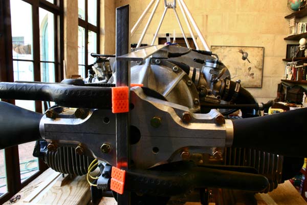
Made
sure the prop was lined up with the fuselage center line and
square .
Turned the prop vertical and checked it with a level.
Turned it to a horizontal position and measured from each
tip to the sides of the firewall and to the tail wheel bolt. These measurements
are within 1/4". |
 |
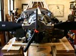
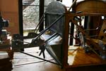
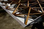
Bolted
the engine mount frame to the firewall. Placed the cross member
above the foot wells in the boot. Cut the slanted 5/8" square
tubing pieces to attach the two motor mount plates to that cross
member.
I find that with the prop hub centered, the engine mount supports
are offset about 1/4 " to the right. Checked and rechecked measurements
and squareness. I will have to call Steve and Jamil about this. The engine does
not seem to be symetrical. |
 |
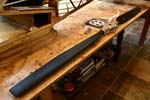
Got
a 3 1/2 x 12 ft carpet remnant to pad the top of my outside work
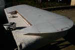
table, to avoid abrasions when moving the covered wings.
Cleaned up extra Poly-tak with MEK. Trimmed fabric with razor
blades along trailing edge and wing tip bow.
Heated iron to 250, and tightened up the fabric, starting
at the ends of the wings toward the center, and working on each side in turn,
to avoid warping. Ironed seams and smoothed small wrinkles and lumps . |
|
|
8
hrs |
|
|
| 18 |
 |
Decided
to start the engine installation over with more precision. Went
to Home Depot and bought a good 12" level(I checked them
for precision and picked the best), and a long perfectly straight
flat aluminum bar .
Re-leveled the fuselage and held it in place with wood squares
screwed into the table.
|
 |
Rechecked
all the center marks with square and level all the way down
the top of the fuselage. Verified all the center marks
lined up from the tail fin to the firewall with the long ruler
and clamped it in place so the front end sticks out just past
the front of the prop.
|
 |
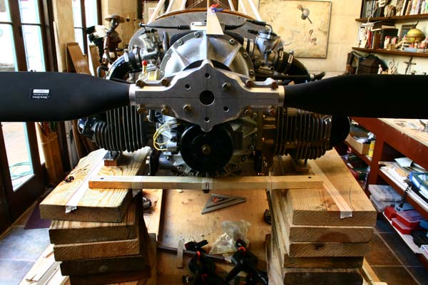
Adjusted
angle of the blades of the prop so the tips are vertical.
Marked the center line of the prop on the hub, as well
as a line at right angle going through the exact center of rotation. Turned the
prop horizontal until that cross line is perfectly vertical , and lined it up
with the end of the stick marking the center line of the fuselage. |
 |
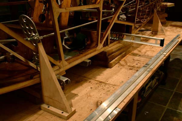
Using
a long ruler clamped in turn to each side of the fuselage, marked
on the blocks of wood supporting the engine the extension of
the longerons. |
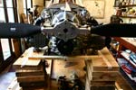 |
These
marks are 24" apart( the width of the fuselage). Marked
the mid point on the cross piece supporting the front of the
engine and keeping it level front to back. The back ends of both
mounting plates touch the tip of the boot, so the thrust line
of the engine is in line with the fuselage. Leveled the engine
side to side using the mounting plates as a reference. |
 |
Checked
that the center fin on the bottom of the crank case lines up
with the center mark on the cross piece supporting the front
of the engine. It does, but the mounting plates are off about
1/8". |
 |
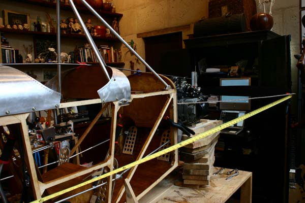
Measured
with a tape measure the distance from the tail wheel bolt to
each tip of the prop, and made sure they were equal within 1/16 ".
Checked the distance between the vertical members of the engine
mount and the tips of the prop. They are within 1/8". Put a small nail on
the center on top of the firewall, and measured to each tip of the prop. They
are less than 1/8".
I didn't think I could do much better, so I adjusted the 5/8" square
tubing pieces to fit. I will tack it all in place to morrow. |
 |
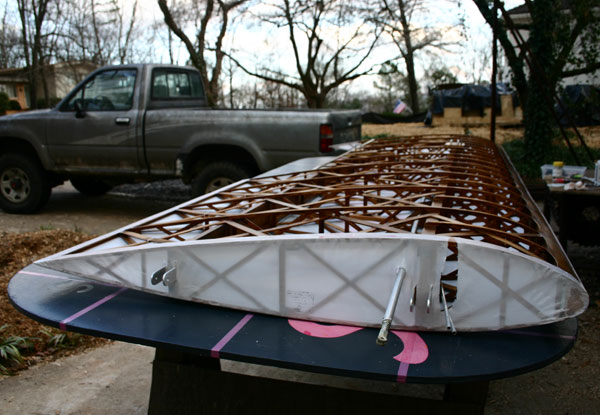
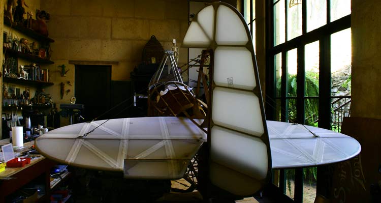
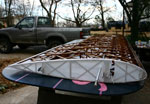
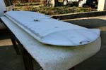
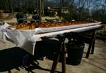
While
the sun is out and it is not too cold, I set up my carpeted table
outside and ironed the covered wing at 350 degrees. Everything
pulled nice and tight .
Ironed the seams some more at 250, and wiped them smooth with
MEK. It will take some more work with the small iron to smooth out all the lumps
and bubbles. |
|
|
8
hrs |
|
|
| 19 |
 |
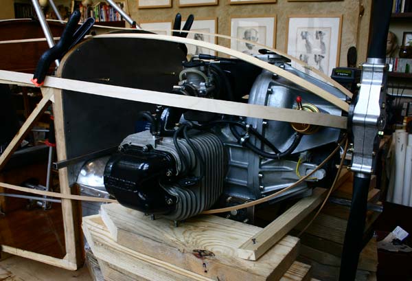
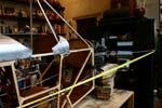
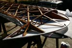
With
the engine bolted in position, tacked the 5/8" square
tubing supports to the mounting plates , and the slanted pieces
to the cross member of the frame.
Cut
the 1/2" round top braces, beveled them to fit , and tacked
them to the square supports. |
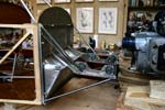 |
Because
the right cylinder is closer to the firewall than the left,
the brace on the right side is shorter than the one on the
left, and I doubled it for strength .
Cut
and beveled the bottom braces , and tacked them in place.
Cut
and tacked in a piece of round tubing to connect the front
ends of the mounts and keep them at a proper spacing. |
 |
The
engine was then unbolted from the mounts, and the assembled engine
mount pulled back and away from the motor with the whole fuselage,
lifting the tail way up to clear the front cross brace.
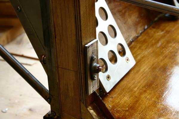
There
is an issue I want to discuss here and will talk to Gene about .
Is it better to insert the bolt from the front and screw it into
a 2 lug fiber nut attached to the vertical member by 2 screws over
an aluminum plate, as shown on the left? That would make removal
of mount easier after the ply sides are glue on. |
 |
Or
is it preferable to insert the bolt from the rear of the firewall
with big washers or a plate, and use the fiber nut at the front
of the firewall, where it can be seen? Removal of mount would
then require a wrench behind the firewall.
If I do that, should I consider using drilled bolts , and epoxying
them in? |
 |
Also,
should the 1/4" holes in the vertical members be redrilled
at 3/8" and fitted with aluminum or steel inserts? I will
ask Gene to morrow.
I
took the assembled engine mount off, removed the Lord mounts,
and took it to my welder, with some 1/16" weldind rods
of 4130 chrome alloy steel . |
|
|
8
hrs |
|
|
| 20 |
 |
Gene
says to leave the holes 1/4" ( no sleeves) and to insert
bolts from the front and use 2 lug nuts behind the firewall.
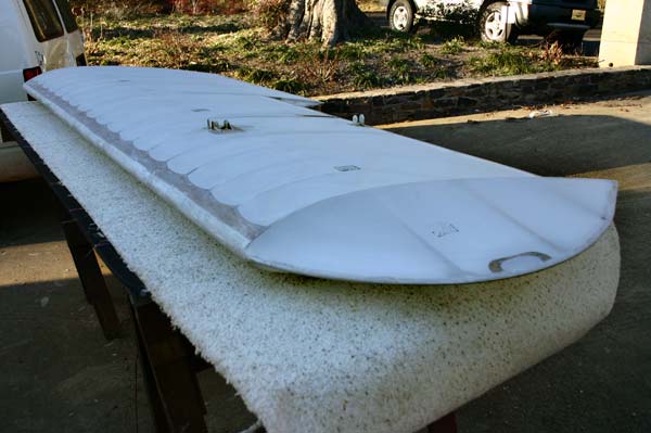
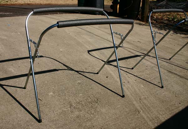
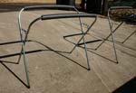
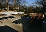
Went
by harbor freight to buy new horses, and ended up buying two
folding stands instead, which are perfect to lay the wings
on to varnish or rib stitch. They have a section of padding
covering the tubing on the top . |
 |
Gave
a soaked in fill coat of Poly-Brush to both sides of the wing,
after some more smoothing at 250 with the small iron. |
| |
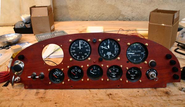
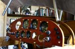
Removed
the panel to start installing the rest of the instruments.
Got
some small brass acorn nuts and brass screws to mount the 2 1/4" gauges.
Mounted
the gas gauge in the center.
Still debating whether to
use a dual CHT and a voltmeter, or 2 single CHT gauges. |
|
|
5
hrs |
|
|
| 21 |
 |
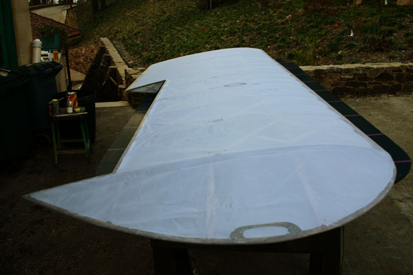
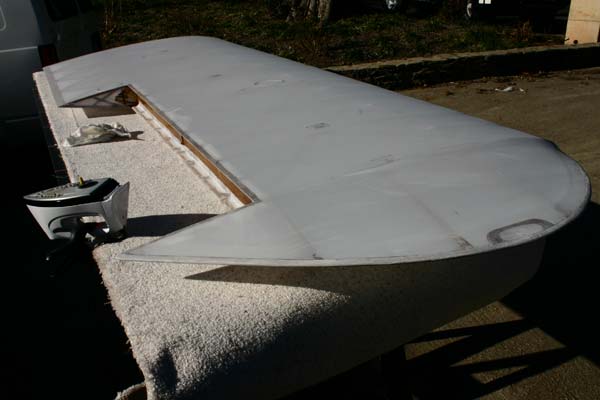
Lightly
sanded the second lower wing and gave 2 coats of Poly-Brush to
the wood areas that will touch fabric.
Snapped a chalk line 1" up from the center
line of leading edge, and taped with 1" masking tape
. Trimmed fabric, pulled it to fit and clamped it on the trailing
edge .
Brushed a 2" strip of Poly-Tak on and quickly
pressed the fabric in it firmly with the palm of the hand in 18"
sections. Used the brush to press in the areas where the glue
has not sufficiently soaked through. |
 |
I
learned doing the first wing that to get a wrinkle free transition
to the wing tip bow curve , it helps to pull the last few inches
up over the chalk line. |
 |
Turned
the wing over and glued the fabric along the trailing edge,
the bow, and to the 1" root strip. Let it dry for a while.
Smoothed
the extra glue with MEK. |
 |
Turned
wing over, and work fabric over trailing edge with the small
iron at 250.
Glued
it to the trailing edge . After it dried, trimmed it with razor
blade. |
 |
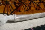
Wrapped
and glued fabric around wing tip bow the same way. Trimmed
along inside edge.
Cleaned
up extra glue with MEK. |
 |
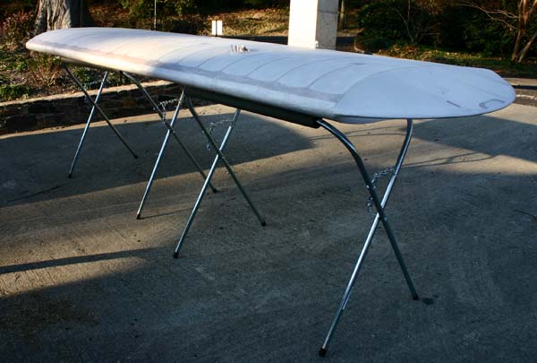
While
the glue dried in the sun on my brand new stands, I got out one
of the top wings and sanded it lightly, then gave it the 2 coats
of Poly-Brush . |
|
|
8
hrs |
|
|
| 22 |
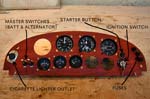 |
Took
panel off, and continued installing instruments , switched ,
fuses, and cigarette lighter outlet, making sure to leave a space
where the cabane supports are against the panel.
Used a standard keyed ignition switch, and a separate starter
push button. Instead of using a standard split master switch,
I opted for a pair of good looking aluminum switches from Auto
Zone. The cigarette lighter outlet will allow plugging an eventual
GPS and radio.
I will order the 3 1/8" Westach Tachometer on Monday.
|
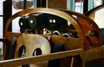 |
Decided
to cut out part of the front seat back panel to have easier future
access to the instruments wiring. I will make an aluminum cover
with swirls to match the existing doors. |
 |
Added
a spacer to make a little more room for the altimeter, glued
it in with the 4 brass stubs to attach the panel. Also had to
remove some material to insert and fit the two lower gauges down
into the panel floor. It will not weaken the structure, as there
is a doubled cross member there already that was added as a spacer
earlier , and turned
out not to be quite sufficent to fit the altimeter when the panel
was slanted. The seat belt blocks are untouched. |
 |
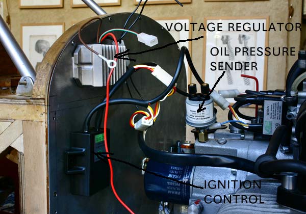
Tentatively
located the Voltage Regulator and the Ignition Control unit on
the right side and top part of the firewall.
Mounted
the oil pressure sender with the metric adapter in place of the
original oil pressure warning light sensor. I might still use
both if I find a T. |
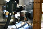 |
Similarly
located the starter relay just above the Starter, and the main
Master Relay to the left of it above the boot.
I
am pretty sure the battery will have to go in the back of the
pilot seat to balance the heavier engine, but it will take about
9 feet of both positive and negative #4 wire to bring the power
from it. It would be so much easier to mount it to the firewall
right above the starter relay... |
 |
The
installed panel is marked to be slightly notched at each end
to fit the two cabane supports and mounting bolts. The fit is
very tight.
Decided
to forgo the Voltmeter for a simple light, and to use 2 Mitchell
single CHT gauges, instead of the Westach dual gauge, which looks
too modern for me. Looks count, and I find my panel design
quite hansome thank you...
Now, if I could only find an oil temperature sender in a 10-1.5
mm size , everything would match.
|
|
|
8
hrs |
|
|
| 23 |
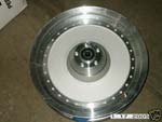 |
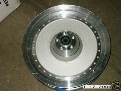
I
went on E-Bay today and looked a more than a thousand Harley wheels
offered for sale or auction . Realized that I had been looking
for wire spoke wheels because it IS the vintage WW1 thing , but
actually liked the solid look of the aluminum 16" "FAT BOY" wheels
better . They are also lighter and surely withstand side forces
much better . I bit the bullet and bought one front wheel outright
for $100. There are several more coming up in the next few days.
I am not sure of the weight, it will hopefully not be too much
. I will have to see about disk brakes for them now. Will I keep
the landing gear now, or design a new undercarriage? |
|
3
hrs |
|
|
| 24 |
|
The
weather is wonderful, sunny and cold, I called my flight instructor
Bob Schrier , and we settled on a 3.30 lesson, just before sundown.
I practiced take offs on the X-Plane simulator, and
manage a number of them without running off the runway. A good omen
may be, we will see this afternoon.
Called Mitchell to inquire about a 10-1.5mm oil temperature sender.
They gave me the part # PS-211-8046 , which I passed on to Aircraft Spruce, as
well as the PS-211-8154 part # for the two CHT 12 mm ring senders for the two
CHT gauges.
Called Westach to order their #Y2ATH7A 3 1/8" TACHOMETER . That should
do it instrumentation wise.
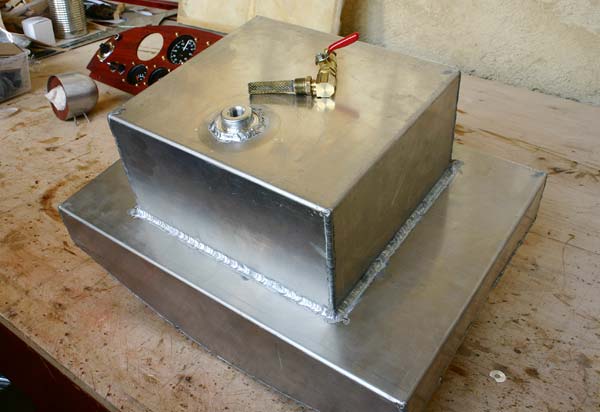
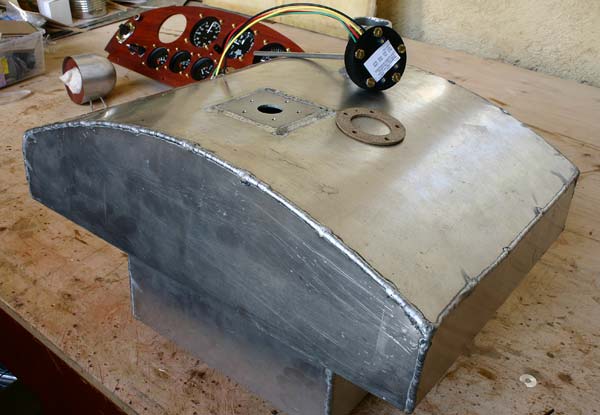
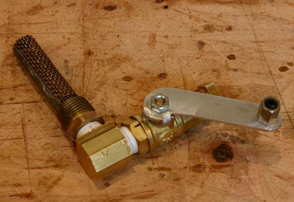
Went by the tin shop to check if my engine mount had been welded. Not yet, but
the gas tank was ready with the new larger 3/8" NTP flange on the bottom that
will take the standard finger strainer. The top is fitted with a welded square
plate to mount the gas gauge sensor.
I read up my flight manuals until it was time to drive to the airstrip for my
lesson.
Well, we flew around the lake and watched the sun set. Had a great time, and
did pretty well actually. I feel somuch better than in October. Yes, it had been
that long!
|
|
2
hrs |
|
|
| 25 |
|
The
weather is still wonderful, sunny and not so cold.I spent
most of the day outside in the driveway covering wings. Glued
fabric to the top side of an upper wing. Glued
fabric to the other side of the lower right wing. Ran out
of Poly-Tak , and won't get any more till Friday, as for
some reason my order was shipped from California instead
of Georgia.
Notched
the sides of the panel to allow the tight fit of the rear
cabane struts mounting brackets .
Drilled
panel and installed the T-handle gas valve control on the extreme
left side. |
The
cable comes out of the back of the panel , and is routed
against the top of the left longeron, through a hole in the
front panel, and around the front to the gas valve handle.
I want the valve to be open when the handle is
pushed in, and closeit by pulling it, so there is no risk
of cutting the gas off by hitting it accidentally .
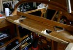
I
also decided to raise the front seat throttle quadrant, as there
was a chance to hit the bottom side of the levers with the
toe of the foot when pushing the pilot's left rudder pedal. |
| The
handle the valve came with had the closed position at 90 degrees,
and the open at zero, which would cause binding. I cut a new
one out of a 3/32" scrap of aluminum(actually the square cut
out of the top of the gas tank where the gauge mounts), with
the open and closed positions at 45 degrees. I gave it
only one stop tab as the original, so it does not have one
for the open position. Bad. Also, it works backwards, so I
will make a new one. |
|
|
8
hrs |
|
|
| 26 |
|
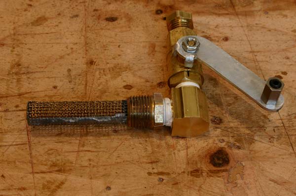
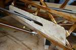
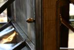
Cut
a new lever for the gas valve with 2 positive stops in the full
open and the full closed position.
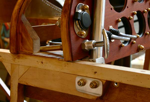
To
the left is the closed position, with the T handle pulled
out. |
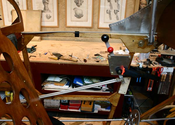
To
the left is the full open position of the lever, with the
T handle fully pushed in.
Drilled
a 1/4" hole and mounted a cable B-NUT for cabin heat. |
| The
front seat throttle quadrant was moved up higher, so the bottom
reversed levers would not interfere with the left rudder pedal. |
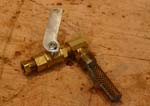
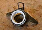
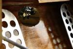
Ground
the outside of a threaded plastic plumbing connector to make
it fit inside the antique winged gas tank cap . I will epoxy
it in place after it is screwed on the gas tank so it faces
forward.
I will need a soft rubber gasket
, and an mount an open bent copper or brass tube on top to keep the tank under
pressure from the wind. |
|
|
5
hrs |
|
|
| 27 |
|
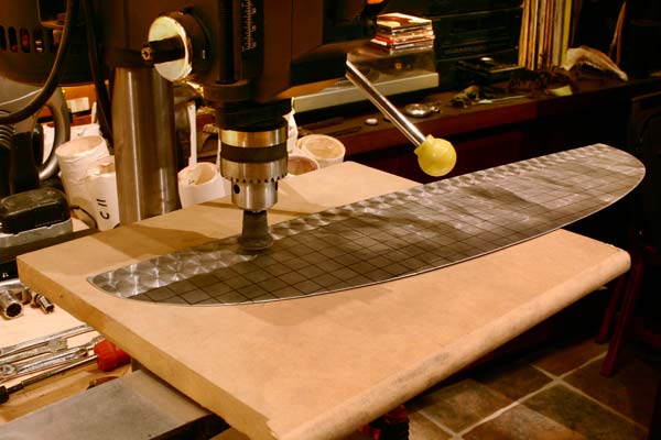
Cut
a piece of aluminum to make a cover for the opening cut out
in the back of the panel.
Drew
a 5/8" grid on it , to be a guide when doing an old fashion
"bouchonne" finish on the drill press. Make sure
the backing board is perfectly flat and even.
I
had to figure out on my own how to do this , so here is
my procedure.
|
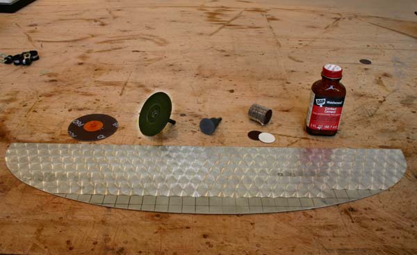
I
had a small 1" rubber sanding disk with a 1/8" shaft and
a set of 1" adhesive backed sanding disks(150 and 220 grit)I
had bought from a model making catalog to use to grind and
polish small bronze sculptures. The rubber disk did not hold
up, so I made my own out of a cheap plastic 3" pad that came
with a set of 3" disks and fiber pads. I cut it down to 1"with
a knife while rotating on a drill. The quick lock hole in
the center was filled with epoxy, and the whole pad was covered
with epoxy. After it dried, it was sanded smooth and
true on the drill press. It
has to be perfect , otherwise the swirls will be off. It
takes very little to mess things up. |
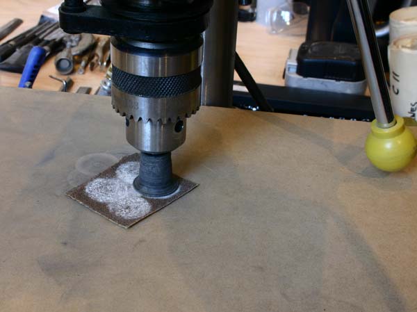
The
disks are stuck to the pad, and the aluminum plate moved 5/8"
at a time row after row so the swirls overlap. You can either line
up the swirls or offset them 5/16" each row. Press lightly, otherwise
the disk heats up and comes unglued . When it does, you have to
clean the residue completely with lighter fluid, re-sand the
disk lightly and clean it with fluid again before sticking a new
disk on. If the disk is still good, you can try to re glue
it on with Weldwood contact cement (applied sparingly to
keep the disk smooth).
You
may also have to shim the backing board slightly to have
a complete swirl . Blow the dust off the metal and off the
board after each swirl. Experiment with a scrap. |
It
is a lot of fuss, but well worth it to me.
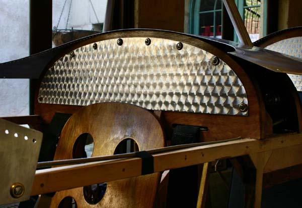
The
cover plate was attached with screws and brass countersunk
finishing washers. That's
it for today, I got to go fly, the weather is still wonderful,
but a storm is coming. |
|
|
5
hrs |
|
|
| 28 |
|
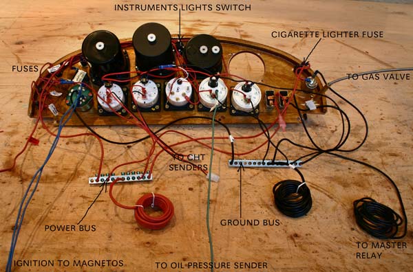
Received
my two Mitchell CHT gauges today , and promptly installed the
into the panel. I am assuming my sensors will ship directly
from Mitchell, since they are special order, but have no comfirmation
of that from Aircraft Spruce. Also received the bus bars, which
are jist 1/16"x 1/2"strips of copper with 8 holes
and no screws or mounting hardware. I think I will use instead
a standard aluminum panel bus bar fron Home Depot. Actually
, use one for the ground and one for the positive , and screw
them into the bottom of the panel.
All I miss now is the tach.
|
Got
an assortment of 16 , 14, 12 and 10 gauge wire in red and
black from Auto Zone, as well as a neat small old fashion
black knob pull switch to turn on the instruments lights,
and wired them through a fuse, even tough I probably will
never need them. But what the heck, they were there! All
the fuses were connected to the power bus bar.
Also wired the posive to the oil pressure
and temperature gauges
through fuses on to the power bus.Connected black leads to them wired
to the ground bus bar.
Used 2 blue wires from the ignition switch
to the blue magneto wires on the engine.
Used
a green wire from the oil pressure gauge to the sender. |
|
|
2
hrs |
|
|
A
number of questions have popped up about engine installation, and Steve
at Central Florida Flyers has been very helpful trying to answer them
:
1. Are my Home Depot 10-1.5 mm
all thread bolts OK to bolt the motor mounts? NO, use grade 12 or atleast
8 . So I ordered from www.boltdepot.com :
Product #6751 , Metric hex bolts, Metric partial thread bolts, Steel grade 10.9,
10mm x 1.5, 50mm
2. Can I turn the prop backward,
since there is so much resistance compared to turning it forward? NO.
3. The gas pump is so high on the front
of the engine and so much higher than the gascolator that I wondered
if there was a need for an electric fuel pump. No, and no primer needed either
.
4. What kind of hose should I use between
the gascolator and the fuel pump
, Aeroquip 303 at 6 bucks a foot, or Aeroquip 601 at 10
bucks a foot? He uses a light weight Aeroquip NAZCAR hose with braided stainless
sleeve and stainless hose clamps.
5. The intake of the gas pump is
on top of it, so there will be a high point on the hose. Is there a chance
for vapor lock . No says Steve, in fact , the loop up keeps it primed.
6. Is the alternator light green
or red? Green.
7. Does he use a split master switch
and separate battery and alternator cuircuits? No, just one Master Switch.
8. Are the two extra little loose
elbows on top of the carbutators
for the choke? Yes, and it needs to be connected with motorcycle cables
and housings, like the throttle. I won't be able to use the stiff Bowden
cable I have. I took an elbow off and still can't figure out how to connect
the choke cables. Verner should supply more detailed instructions.
9. Is the Power Sonic 18AH battery I
bought strong enough. Probably not ,says he, though it depends on the engine
.He uses at least a 21AH. A possible option I suggested was to use an extra
bigger 12 volt auto battery on the ground to crank up the engine at first , then
when it is warm, use the smaller one on the plane. Some people have done that.
10. Using
aluminum bus bars from Home Depot is OK.
11. Where to get a face plate for the prop as
recommended by Warp Drive? He will sell me one for $10. |
|
| 31 |
Wasted
a lot of time today going around motorbike shops trying to find
throttle and choke cables for the Verner.I had not thought that
most were closed on Monday , some had closed down . Ended up getting
a brake cable and two thinner shifting cables from the bicycle shop. |
|
2
hrs |
|
|
| TOTAL 935hrs |
|
|