|
| C
O N S T R U C T I O N L O G |
|
| N
O V E M B E R 2 0 0 4 |
|
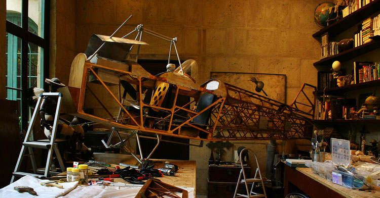 |
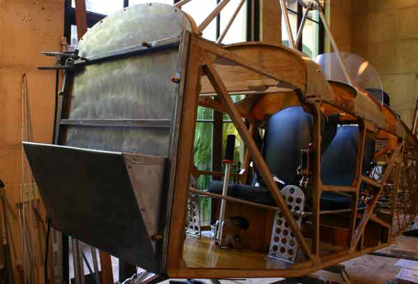
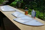
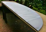
| Wings
off. About ready to cover, and back at work on the fuselage getting ready
for the engine installation. |
|
| 1 |
Glued
rear plates for top horizontal member.
Drew the engine mounted in relation to the firewall, so the
cowling would flow nicely and the CG would be as far back as
possible. Cannot do much better than Jamil. Sent
a copy to Gene with some questions. The e-mail with answers is
below. |
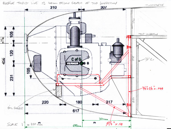 |
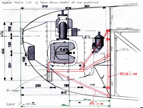
Gene,
Here
is a preliminary side view of the VERNER engine installation
on my Classic. As you can see, in order to fit the carburators
inside the aluminum cowling and to keep nice flowing lines,
I have to place the engine thrust line about 1 3/4" below
the center of the top longeron . Is that acceptable?
YES This
is about as close to the firewall as I can get the engine,
and it places the center of gravity of the engine about 13" in front of the
firewall and the prop flange about 27.5" in front of the fire
wall. How does that compare to the 582 installation in your bird,
and does it seem OK to you? The weight of the engine including
all accessories is about 142lbs.
This
is close to what the 582 is, only a little heavier. My
battery is about 12 lbs, should I plan on putting it behind
the pilot seat with a 7 foot #4 battery cable to push the CG
back, or do you think it might be Ok right behind the firewall
between the rudder pedals?
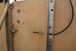
Put
the battery in last. It may have to go behind the seat. I
am not using stringers on the side of the fuselage, and therefore
no curved wood strip on the outside of the front members, so
I re-enforced the front vertical members with two 3/8" plywood strips to the inside and
to the back. I will add a 3/4" square tubing brace across the
top of the engine mount, and put two 1/4" bolts through the top
vertical member, which I also re-enforced with 3/8" plywood
plates in the bolts locations, unless you tell me it's a bad
idea.
Should
be ok
What
kind of welding rods should I use to put the engine mount together,
plain #7, or heat treatable 32CSM. Should the welds be heat
treated? What about the expensive vacuum melted welding wire?
Don't
have an in house welder. Can not answer.
Thanks.
JJ |
 |
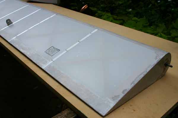
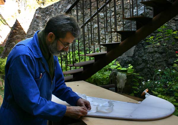
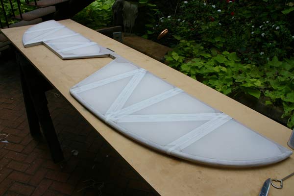
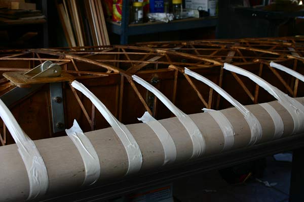
Even
after a week drying, the epoxy varnish was still lifted
by MEK, so I had to strip it off the 2 ailerons. I will
just glue the fabric directly over the Polyurethane varnish.
Gave
2 coats of Poly-Brush to the leading edge ply, trailing
edge, and end pieces of ailerons.
Started
covering an aileron. Had to start over because I cut
a slit in the fabric on the other side trimming along
the trailing edge piece.
The
straight from the can Poly-Tak is too thick to soak through
the fine weave light weight fabric , so I added some
reducer/ retarder to it, which helps,and also makes it
easier to brush on , and slows the drying some.
Even
working outside, the fumes are making my head and liver
hurt . I may have to shave my beard off to get a good
fit for the respirator... |
|
|
|
4
hrs |
|
|
| 2 |
 |
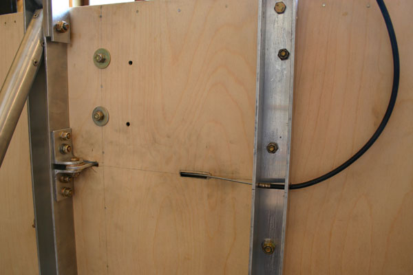
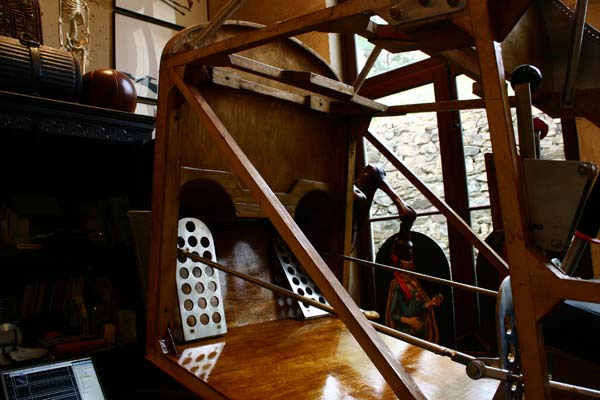
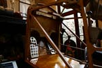
Turned
plane on its side. Designed and started to install heel brakes
to replace the toe brakes. That will allow me to move the pedals
forward of the passenger seat. The bracket supplied by Fisher for
the toe brakes makes a perfect pedal. It is hinged under the floor
through two slots, and the L shaped hinge brackets are bolted to
the rear of the forward landing gear channel , so only the pedal
stick out of the floor. |
|
3
hrs |
|
|
| 3 |
 |
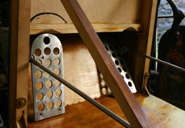
Polished
all the heel brake parts. The brake cable goes throuh the floor
at an angle, and through the landing gear chanel, which also stops
the cable housing.
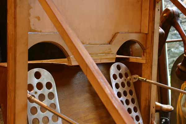
I
hate those cheap looking plywood rudder pedals, and will make new
aluminum ones. |
|
4
hrs |
|
|
| 4 |
|
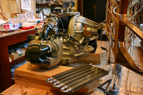
| Got
a call this morning that my engine had arrived at Fed Ex Freight,
and went to pick it up.After uncrating, I found that the plastic
top of the right carburator and bent aluminum tube guiding
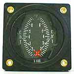
the throttle cable in were broken. Also, the gauges are not
the Verner gauges, and are round
2" type , which will not fit my panel. Steve said I could
return them and buy my own. |
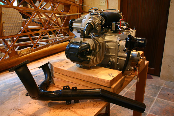
| The
exhaust is not the one shown on the Verner site, and I like
it a lot better . It is a straight swiss type pipe that will
exit at an angle at the bottom of the cowling near the firewall. |
Installed
the old rudder pedals to test the brakes. Had to lengthen
the pull rods with a piece of 1/2" tubing. It feels
pretty comfortable.
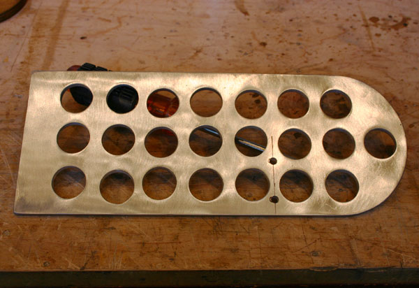
So
I bought a piece of 3/16" aluminum to make new rudder
pedals at the Metal Supermarket. They even cut the 4" blanks
for me. Made
the first pedal , with 3/4" holes to lighten them.
I moved the pull rod braket to the back of the pedal and
up a little so it attaches between holes. tThat will shorten
the travel of the pedal a little. The pull rod between
the front and rear pedals will attach to the same bolt |
|
|
4
hrs |
|
|
| 5 |
|
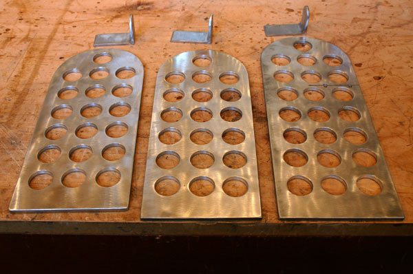
| Made
the remaining 3 pedals and brackets. Went to bigger 1" holes. |
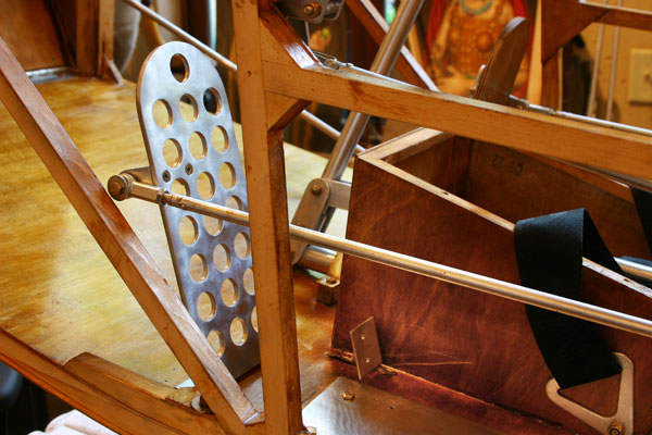
| Installed
the 2 rear pedals. I may move the attach point to the floor back
so the pedals are not so vertical. |
|
|
6
hrs |
|
|
| 6 |
|
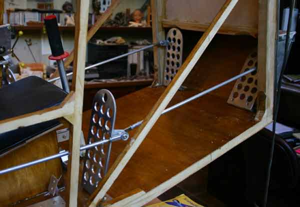
| Installed
the front
rudder pedals. Had to notch the top of the boot to fit them. The
boot is really too low for a size 10 foot tomanoeuver the pedals
safely, the toe catches. |
| I
think I will have to cut out a moon shaped section of the firewall
and boot above each pedal and box it with a curved piece of
plywood. That means engine mount lower horizontal piece will
have to move up the firewall. |
|
|
4
hrs |
|
|
| 7 |
 |
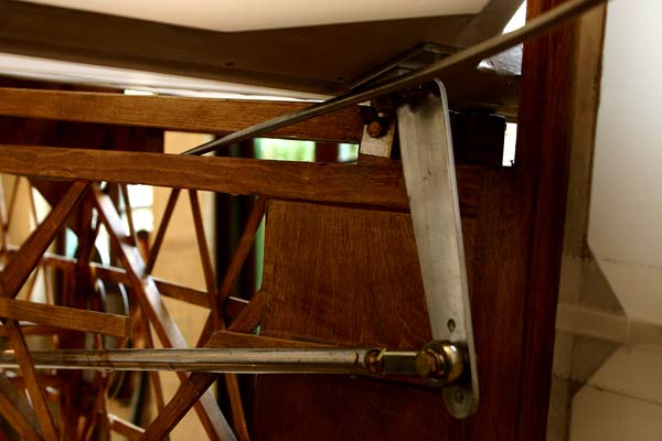
Started
working on the engine mount, using the 5/8"x .049 wall square tubing
. Drilled tubing and tacked 3/8"x 7/8" long tubing sleeves. Drilled
holes in firewall and
attached the two vertical pieces and the horizontal piece with
long AN4 bolts. Tacked them together.
Redrew
the engine mount to accomodate the taller boot, as shown below.
It actually simplifies the design. Also increase the length of
the 1/2" braces . |
|
4
hrs |
|
 |
|
| 8 |
|
| Ordered
a piece
of flat 4130 steel 3"x36" to make the motor mount brackets. |
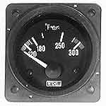
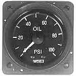
| Tried
to figure out what gauges to order and what size senders I
need. I like old fashion gauges like the Mitchell oil pressure
and oil temperature square 2 1/4" gauges.The holes
for the senders on the Verner are metric sizes, so I will
probably need adapters for the standard 1/8"NTP
senders. The oil temperature sensor is 10 x 1.5 mm thread with
a 1" tip. The oil pressure, I don't know, and I can't
unscrew the plug, so I sent an e-mail to VERNER to ask. |
| Ion't
like dual CHT gauges a whole lot, but since there is only space
in my panel for five 2 1/4" gauges, I may have
to use one. The alternative is to use a single gauge and switch
from one cylinder to the other, or not to use a voltmeter.
The thermocouples have to fit a 12 mm spark plug. |
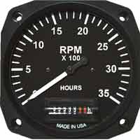
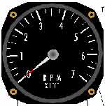
I
want a full sweep 3 1/8" tachometer and hour meter with
a maximum RPM of 5500, that will work with the 2 cylinder
electronic ignition. Sent e-mails to Aircraft Spruce, Westach
and UMA for info. |
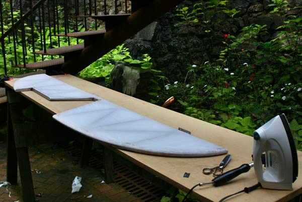
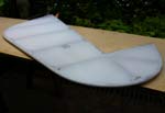
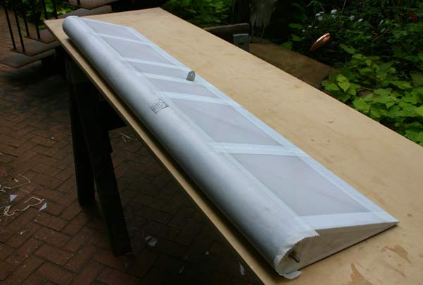
Finished
covering the first aileron shrunk the fabric, and gave it
a sealing coat of Poly-Brush.
Gave
a coat of Poly-Brush to two more ailerons. |
|
|
4
hrs |
|
|
| 9 |
|
| Had
an answer
from Verner this morning: the oil pressure sender has a 10
x1 mm thread. Now I need to find out the size of the Mitchell
probe.
Also
received the 1/8"x 3"x 36" piece of 4130 steel.
It weighs 4 lbs . Drew the Lord mount support bracket on
it.
Gave
a second coat of Poly-Brush to the wood. Covered the other
3 ailerons . |
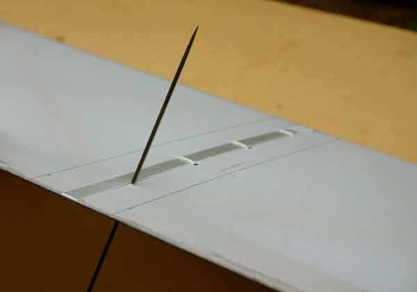
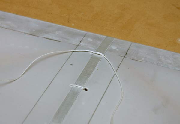
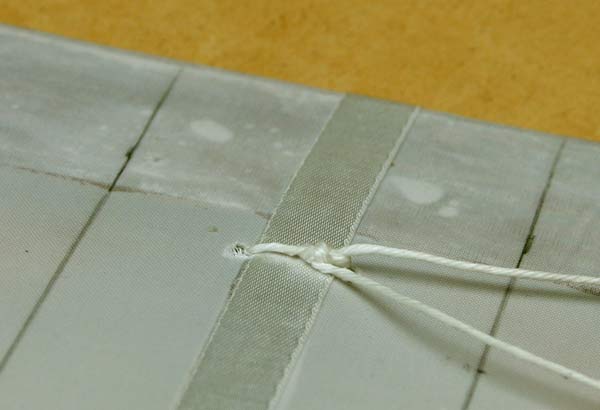
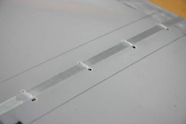
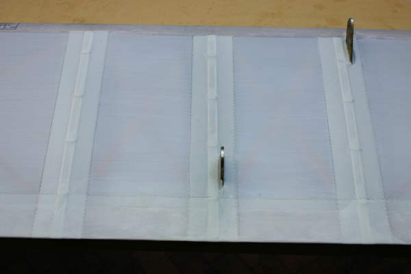
| Attached
adhesive 3/8" polyester rib reenforcing tape, and punched
holes in fabric every 2 1/2" , starting 1 1/4" from the spar.
Practiced rib lacing with the modified Seine knot. I think
I got it right, but will run it by Dick Simpson when I get
a chance. |
|
|
8
hrs |
|
|
| 10 |
|
Finished
rib lacing the first aileron. Put some Poly-Brush on the ends
of the 3/8" tape to keep them from unraveling.
Brushed
the seal coat of Poly-Brush on the other 3 ailerons.
Brushed
2 coats of Poly-Brush on stabilizer frame. Covered the stabilizer
with one single width of polyester wrapped around the trailing
edge and glued to the curved leading edge . Ironed seams
smooth, wiped all with MEK |
Put a
seal coat of clear Poly-Brush on top side of stabilizer.
Took
the Lord mount mounting plates to the tin shop to have them
cut and punched. The mounting bolts are 10 x 1.5 mm . |
|
|
8
hrs |
|
|
| 11 |
|
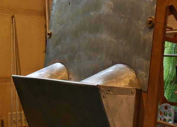
Cut
1/2 circles out of firewall and top of boot to make room
for my big feet . I quote Gene: " The front seat
of the Classic is not for you guys with big feet. Don't see
a problem cutting out a 1/2 moon and gluing in a piece of
3/4" ply cross member across the top of the cut out. Rather
then moving the mount down, I would cut out the top of the
cowl and glass in a couple bumps for the top of the carbs
to into. nicely shaped bumps in the cowl even look good some
times. ".
Cut
piece of 1/2" plywood to re-enforce firewall, and glued
it in place.Fitted
1/16" curved filler pieces. |
Got
an e-mail back from Westach suggesting I use the 3 1/8" Model
#Y3ATH7A tachometer/hourmeter, made for 2 or 6 pulse alternator
operated, 0-7000 RPM . It costs $208, plus red line markings. |
|
|
4
hrs |
|
|
| 12 |
 |
Finished
fitting and glued in 1/16" plywood curved foot wells.
Cut
and adjusted metal covers, and glued them to plywood.
Notched
firewall and boot metal covers to fit . |
|
4
hrs |
|
|
| |
| 13 |
|
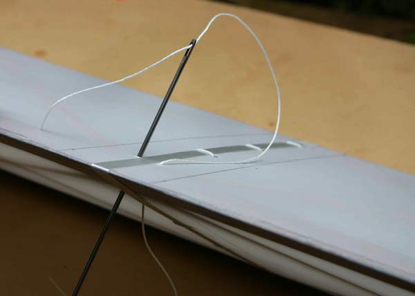
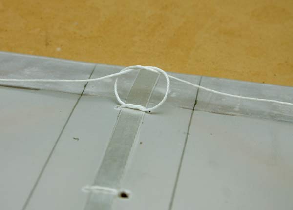
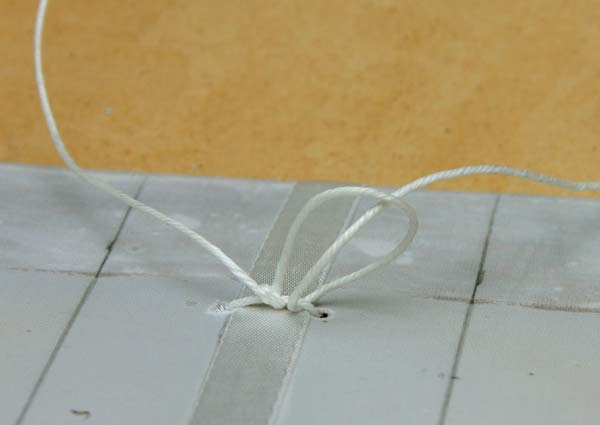
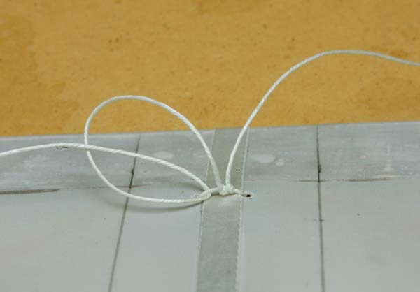
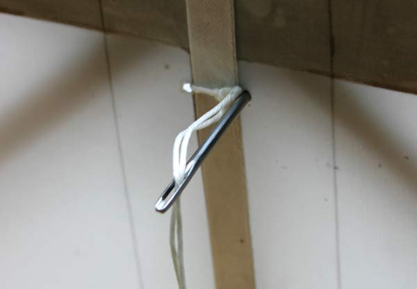
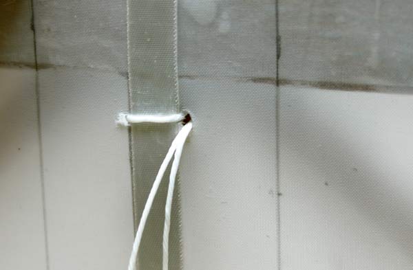
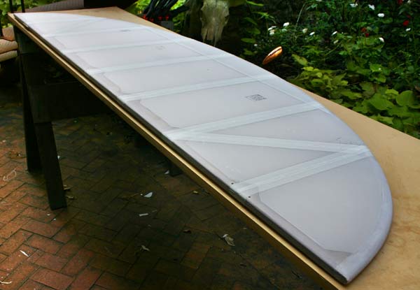
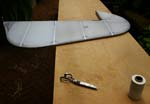
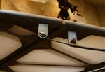
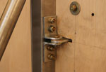
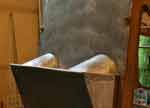
| Rib
laced ailerons . Decided that rather than doing the modified
Seine knot and running a continuous cord, it was easier to just
use a single lace with a square knot and 2 half hitches to lock
it. Then pull it inside, as shown above. |
 |
Taped
ribs with Poly-Fiber light weight 2" pinked tape . It is
expensive, but looks better than the cheaper medium weight
tape I had bought first. And it matches the fabric exactly.
Started
rib lacing the stabilizer. |
|
|
4
hrs |
|
|
| 14 |
 |
Finished
rib lacing the stabilizor.
Taped
the ribs with 2" light weight
Poly-fiber tape. |
|
3
hrs |
|
|
| 15 |
|
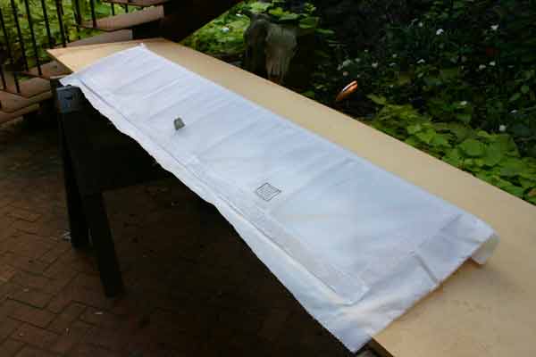
| Covered
elevator with a single piece of fabric wrapped around
the leading edge and overlapping at the trailing edge. |
Covered
one side of rudder , let it dry.
Ironed
seams smooth with 225 degrees iron, and glued other side
on. |
|
|
6
hrs |
|
|
| 17 |
|
Trimmed
fabric around rudder by pulling it against a sharp razor blade.
They wear out very quickly.
Ironed
seams flat at 225.
Cut
four 7" wide pinked strips of fabric to cover leading edges
of ailerons. |
Shrunk
rudder fabric at 250 and 350.
Gave
a seal coat of Poly-Brush to both sides of the rudder.
Taped
ribs with 3/8" tape. |
Shrunk
elevator fabric at 250 and 350.
Put
the seal coat of Poly-Brush.
Put
3/8" tape over the ribs. |
Rib
laced the rudder lace by lace with short pieces of lacing cord.
Pulled knots inside.
Glued
2" tape on top of laces. |
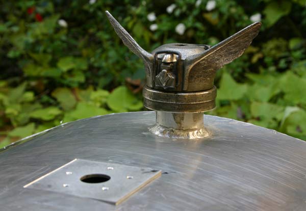
Cut
a square hole in top of gas tank to weld gas gauge flange.
Found
a nice old aluminum radiator cap with wings on e-bay that
will make a good gas tank cap. I will have to epoxy it to the
filler neck , mount a forward facing vent in the hole on
top, and find a soft rubber gasket. |
|
|
6
hrs |
|
|
| 18 |
|
Rib
laced the elevator.
Taped
ribs with 2" tape. |
Glued
a 7" strip of light weight fabric over the leading edge of
all four ailerons.
Glued
4" trailing edge tape on last two ailerons.
Trimmed
ends about 3/16" and wrapped around edges with Poly-tak. |
|
|
6
hrs |
|
|
| 22 |
|
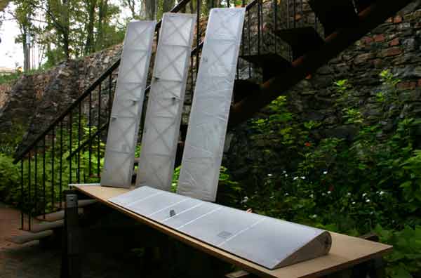
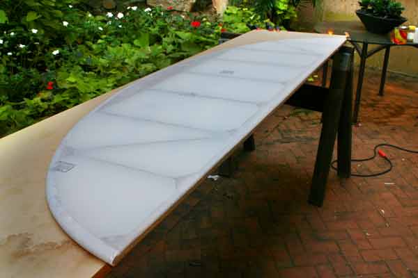
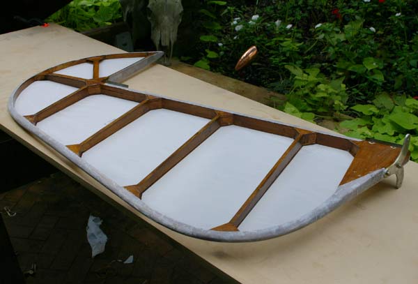
Cut
a new set of 1/8" plywood nose ribs for leading edge
of defective wing.
Glued
them in place.
Wet
two 6"strips of 1/32"plywood and put them to
dry in the bending jig. |
|
|
3hrs |
|
|
| 23 |
 |
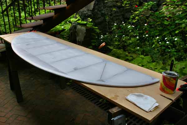
Fit
the leading edge ply, marked ribs, and varnihed inside of
leading edge except for the glue lines.
Sanded
front rudder pedals wells, and varnished them, as well as
back of firewall. |
|
|
3hrs |
|
|
| 29 |
|
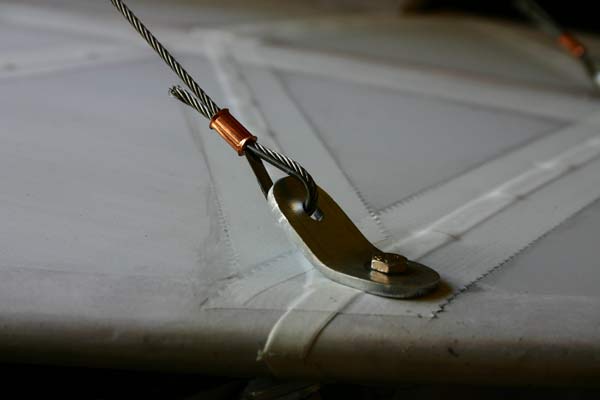
Installed
the covered stabilizor, elevator and rudder.
Made
one of the tail wires out of 3/32" cable and a turnbuckle. |
| Mounted
the elevator horn. Added a flat aluminum plate to increse the
mounting surface. Made two cardbord jigs at 20 degrees
and 25 degrees to check maximum travel of elevator: 20degrees
down and 25 degrees up. In order to get that with full
movement of the stick , I will have to use the middle one out
of the three holes pre-drilled in the horn. Riveted a rod end
to the push/pull rod, and used an Aurora bearing to connect
it to the elevator horn. |
Installed
trim tab and hardware .
Adjusted
the rod ends between front and back rudder pedals so the
front pedal would act as a rudder stop when they touch the
floor of the boot. |
|
|
6hrs |
|
|
| 30 |
|
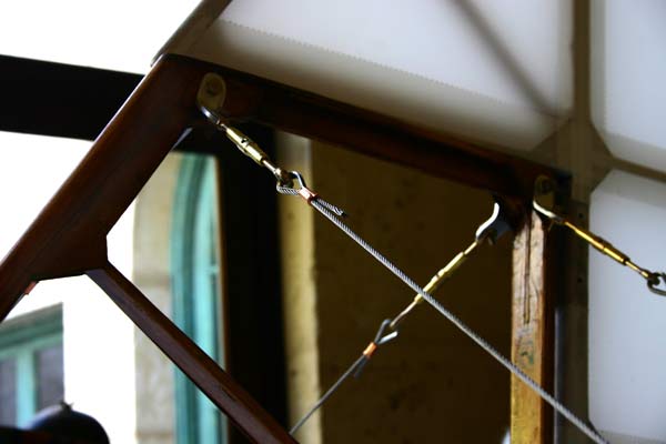
Made
the rest of the tail wires using copper Nicopress sleeves
and brass turnbuckles.
|
I
will cover the piece of raw wire with a leather wrap.
|
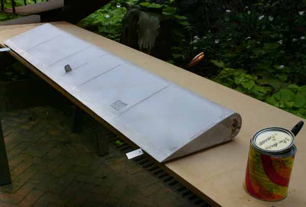
| Glued
the wing leading edge plywood on. I find 1" masking tape does
a fine job of holding it tight untill the T-88 sets. |
|
|
6
hrs |
|
|
| TOTAL 837hrs |
|
|