|
| C
O N S T R U C T I O N L O G |
|
| A
U G U S T 2
0 0 4 |
|
 |
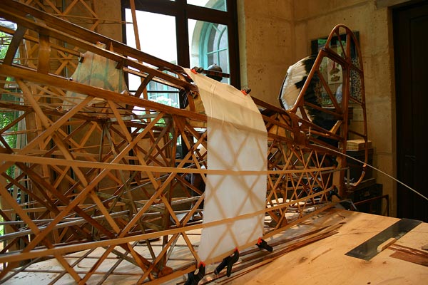
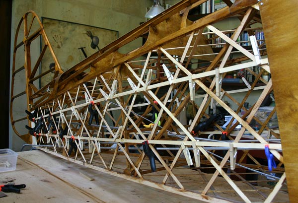
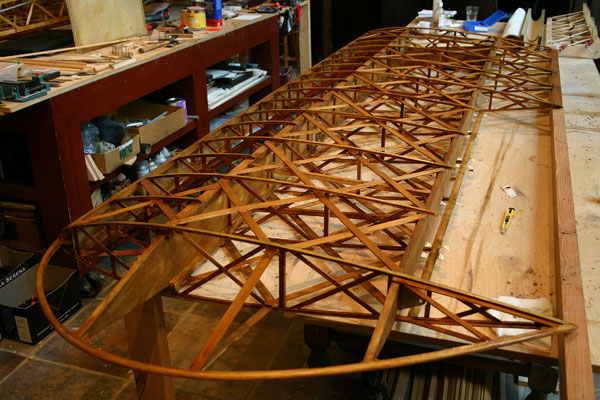
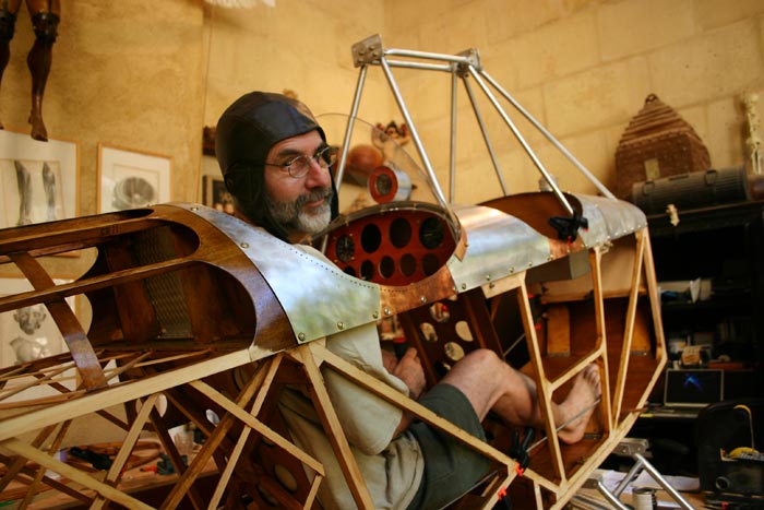
| The
goal (this is Stefan Wode's naked Classic in Germany) |
|
\
| 1 |
|
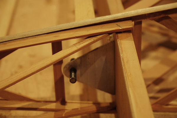
Flattened
tubes ends as per blue prints, but found they tend to crack
at the hole. I don't think T6 is meant to be crushed in a
vise. I will have to ask FFP if theyhave a new design, or
come up with a new way myself, like bolting 1/8" plates to
the side of the tubing. |
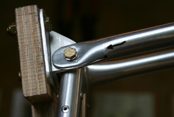
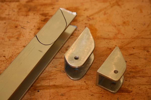
| The
front brackets do not seem big enough to me . They are identical
to all the other cabane brackets, which simplifies manufacturing,
but if I notch the heavily doubled tubes to fit around the
bolt ends, there won't be much material left around the hole.
I will order a piece of 1" channel and lengthen the bracket
so the hole can be moved down some. |
|
|
3
hrs |
|
|
| 2 |
|
Drilled
1/8" holes all the way around cockpit openings , 3/8 "
from the edge, to lace the future leather trimmed padding. |
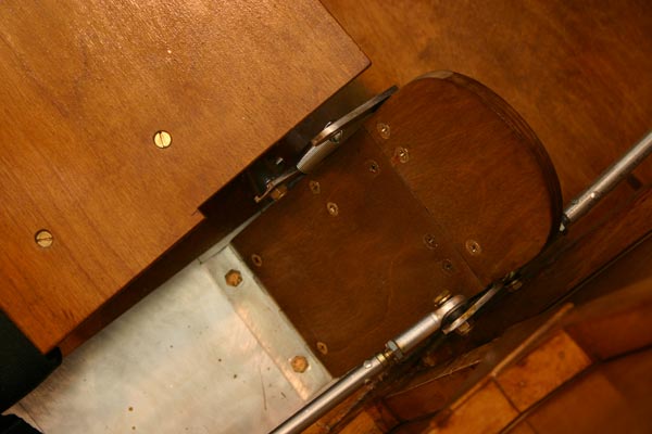
Cut
out luggage compartment door in bulkhead behind pilot seat,
and made an aluminum door with aluminum piano hinge mounted
with brass screws.
Varnished
bulkhead, turtledeck, front seat, pedals, and rest of floor . |
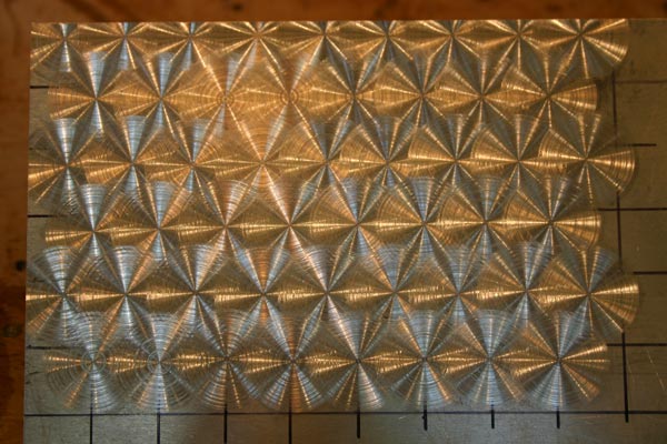
| Experimented
with swirl patterns on aluminum using a 1" sanding disk
on the drill press. 120 grit seems to work best, with a staggered
5/8" grid. |
|
|
6
hrs |
|
|
| 3 |
|
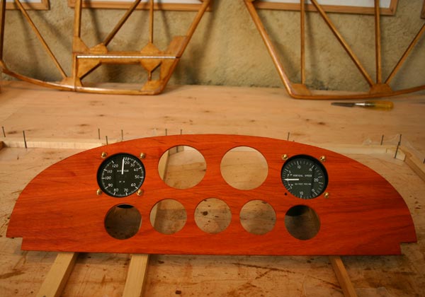
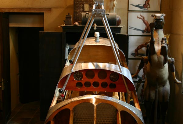
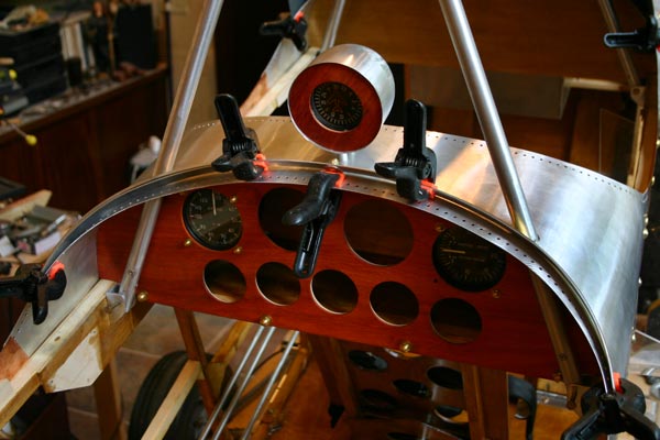
Cut
a piece of padouk to panel size and planed it down to 3/32",
after attempting uncessfully to slice it in half . Drilled
3" holes to match 3 1/4" holes in plywood panel
, added 2 1/8" holes and matching 2 1/4' holes in
plywood .Mounted airspeed and vertical speed gauges with
brass acorn nuts. Looks real good! |
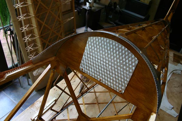
Sanded
overlapping circles on luggage compartment aluminum door
with 1" disk on drill press, sealed it with clear gloss
lacquer, and installed with brass screws and copper washers.
Looks real good!
|
| Cut
3" wide strips out of olive green leather scraps to use
around cockpit openings. Will have to mix 2 kinds to have
enough. |
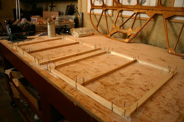
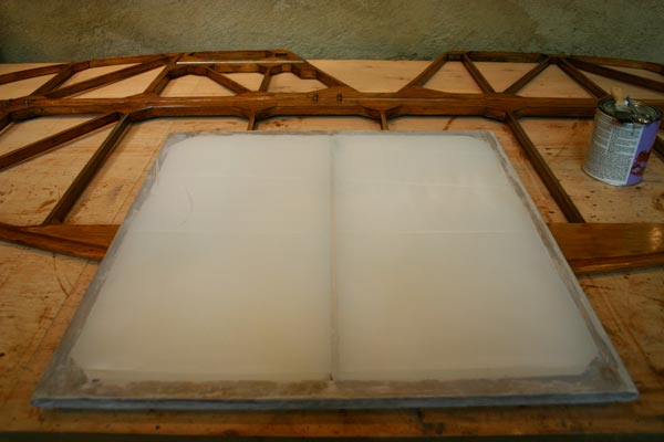
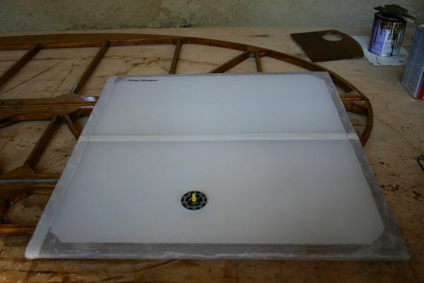
| Made
two 24"x24" frames to stretch fabric on and test
clear dope finishes. |
|
|
8
hrs |
|
|
| 4 |
|
Added
missing blocks and ply gussets to top longeron at firewall.
Gussetted tank support, added spacers in front.
Varnished
the 2 frames.
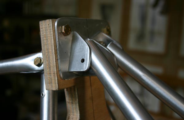
Made
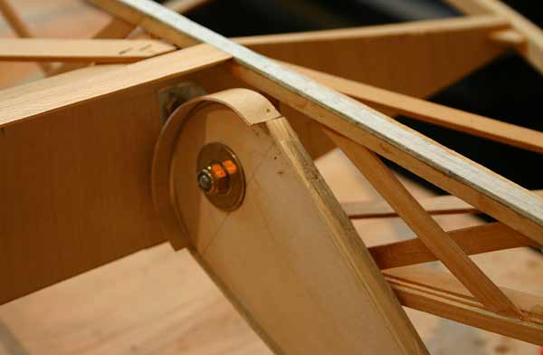
new larger brackets for front of cabanes out of 1" channel. |
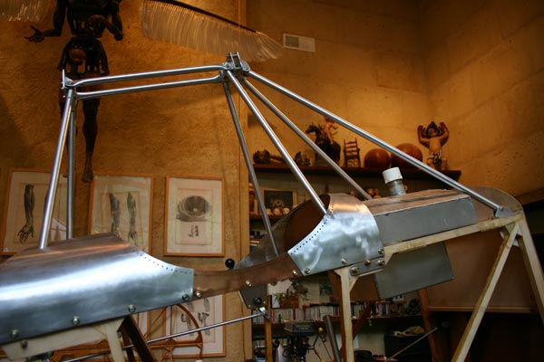
Finished
cabanes , took down the plywood jig and put them back up
with 3/4" spacers between plates.
|
Installed
turtledeck aluminum pieces, cut holes to get cabanes through.
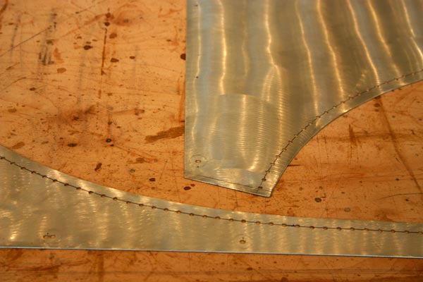
Worked
on cardboard pattern for front turtledeck. The holes for
the cabanes have to be very oblong. Cut 2" hole for gas tank
neck. Traced pattern on a sheet of .020 thick 6061T6 aluminum. |
|
|
8
hrs |
|
|
| 5 |
|
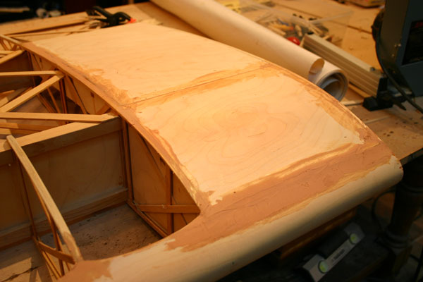
Cut
out of .020 thick 6061T6 aluminum the front turtledeck
cover. Light, but plenty stiff once bent around the curve.
Sanded
and varnished frames a second time. |
Cut
, fit , and install firewall aluminum pieces .
Spackled
and sanded elevator and stabilizer unit before second coat
of varnish. |
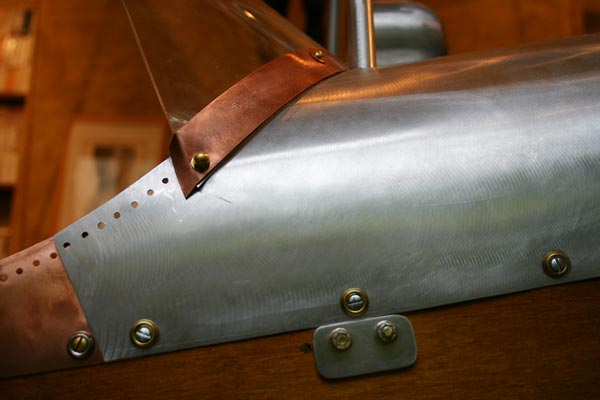
Cut
tentative cardboard patters for winshields. I like the
swept back look. A simple curved piece of plexiglass should
do it , attached to the turtledeck with small angle brackets.
Or better, a fitted copper piece all the way across the
bottom of the windshiels. The bent in the plastic should
keep it stiff enough.
|
|
|
10
hrs |
|
|
| 6 |
|
Cut
a padauk circle with a 2" hole to fit compass in aluminum
bullet I had , re-enforced with 1/16" plywood , and
mounted above panel on turtledeck in front of windshield
with two long metal screws through 3/8"x 3/4" tubes. Padded
interior with cotton to suspend compass and protect it
from vibrations.
|
Stretched
fabric on one of the frames after coating it with 2 coats
of diluted Poly-Brush. Used Poly-Tak to attach the fabric
, and pressed it down in the wet glue. Pulled it flat ,
but not tight. Messy, I need to get rubber gloves! I also
need to get an iron and a thermometer to calibrate it.
Sanded
and put a second coat of polyurethane on one side of stabilizer/elevator
assembly. |
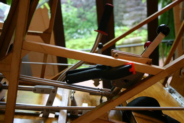
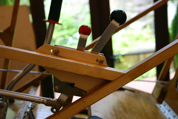
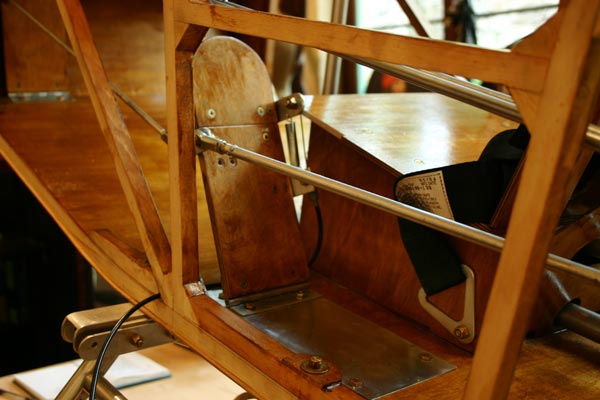
Added
3/4"x2/4"brace to mount pilot throttle quadrant
lower , more or less at elbow level, where it fits comfortably
in the hand. The front quadrant will move down too, but
not so low as to interfere with the rudder pedal. |
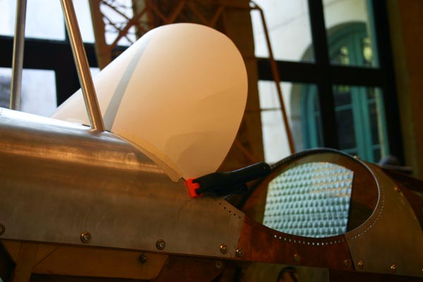
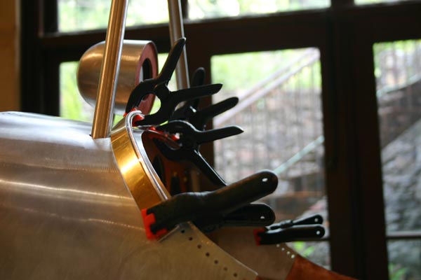
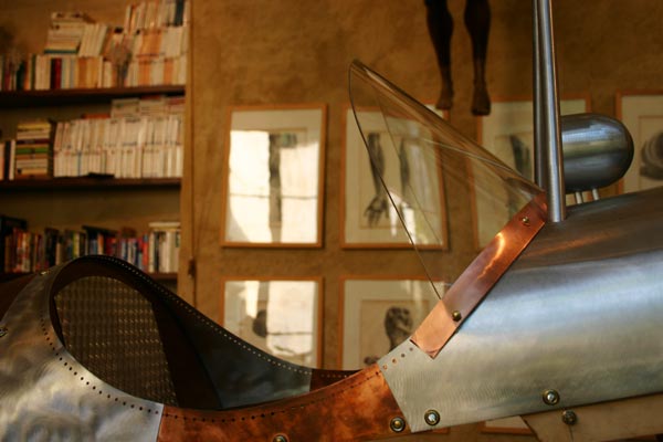
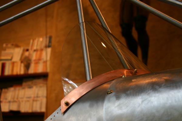
Cut
and bent a 3/4"x1/16" aluminum strip and brackets to attach
bent plexiglas windshield.Cut out pattern out of an old piece
of 1/8" plexi .
I
may end up using a thinner and more scratch resistant polycarbonate
. Will use a 1" strip of brass or copper in front of the
plexi. |
|
|
8
hrs |
|
|
| 7 |
|
Made
5 small angled aluminum brackets to attach it to the turtledeck.Went
by the tin shop to have neat 1" copper strips cut.
Used a 1 " wide plexi strip as a spacer to drill the
holes through the copper, the alu strip and the brackets,
keeping everything nicely curving around the deck with
a good slant. Installed windshield. |
Added
1/4" spacer and 1/8"ply plate to bolt quadrants to. Installed
quadrants in new lower location. Much better, they fall
naturally under the hand.
|
Added
1/2"x1/2" strip on top of existing strip on top of boot
to have something to screw the aluminum firewall panel
to(the screws just went through the 1/8" plywood firewall). |
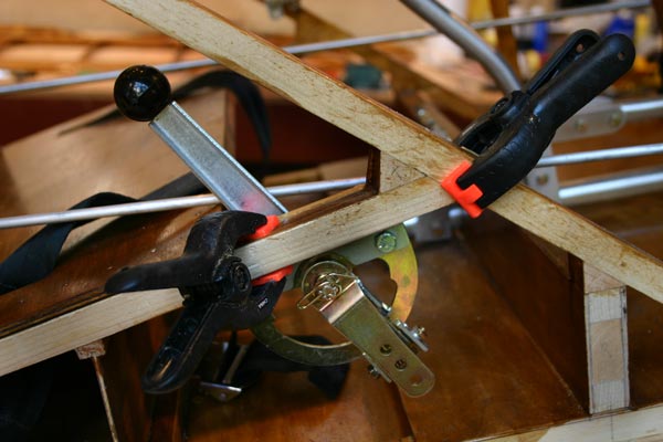
Debated
with Gib wether the trim lever I got would work the right
way: lever forward>push cable> tab up> elevator down>nose
down, seems OK. I guess I will use that locking lever even
though it is heavier than the advertized 8 oz. Glued a
1/4 strip to the side of the member to the right of the
pilot seat to be able to bolt to it.
|
|
|
8
hrs |
|
|
 |
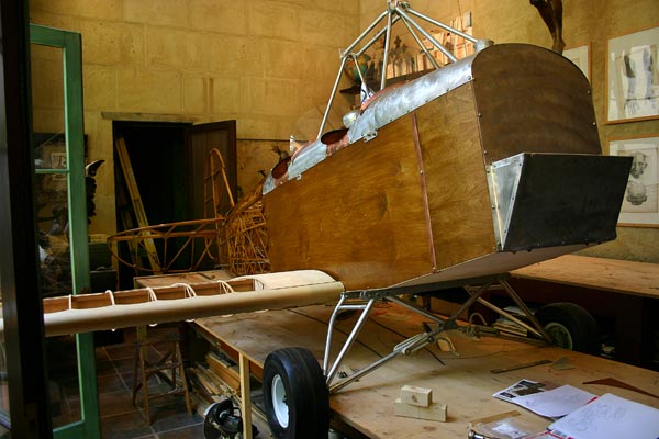
| Just
couldn't help! |
|
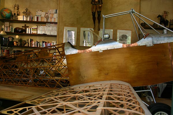
| I
have pretty much decided to do away with all the stringers that allow
to round out the fuselage, and just go for the boxy WW1 Nieuport look.
That would alow me to keep the varnished plywood sides and bottom exposed,
with decorative brass nails and screws, and may be a couple of brass
or copper strips to cover the fabric/plywood seams. I called FFP to
see if Gene sees any problems with that, and he seems to think it is
fine, even though he does not know of anybody having dispensed with the
rounding stringers. That should save a few pound and make up for some
of my cosmetic add ons. |
|
| 9 |
|
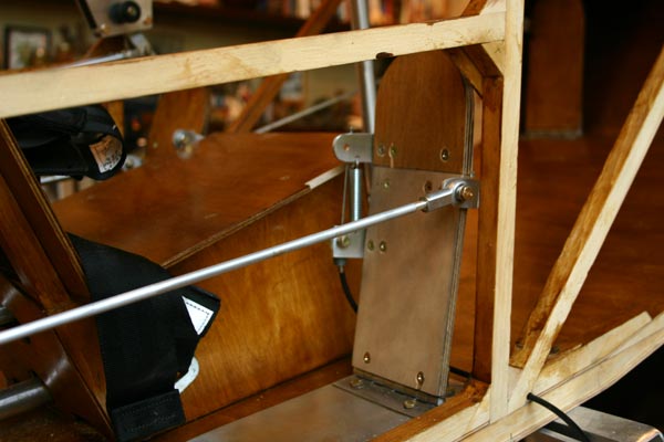
Installed
front windshield, same as back one, only smaller.
|
Installed
aluminum plate on floor below rudder pedals , and moved
pedal back and a little in so bolt would clear member.
Also had to trim the passenger seat a little on each side
so the toe brake bracket would not rub.
Shortened
travel of pedal by moving the bracket up about 1" to
the level of the hinge bolts. |
Made
right rudder pedal with toe brake to match the left one.
Shortened
push/pull rods so neutral position of pedals is more vertical,
so the toe brakes can be operated with full rudder. |
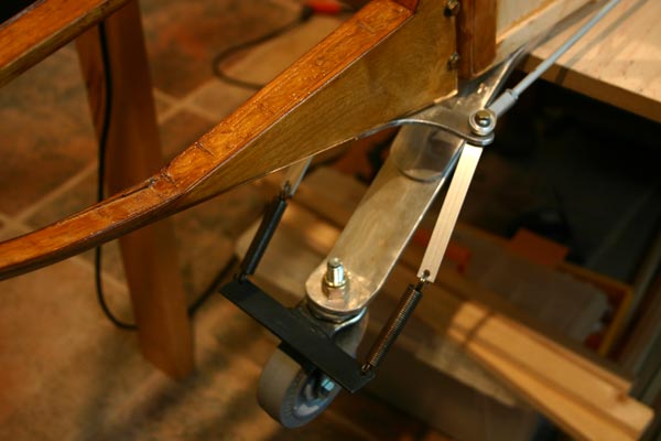
I
need to figure out the best way to attach the tail wheel
to the rudder push/pull rods. Just to see, I made two flat
1/2"x1/8" connecting rods attached to each side of the
rudder horn , and to the brackets of the tail wheel with
the supplied springs.Kinda works... |
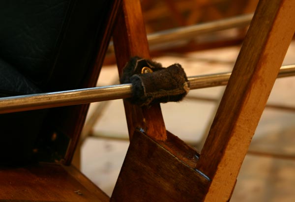
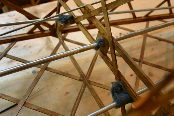
I
got the idea from Buddy Tollison to use sheep skin guides
for the push rods, as was apparently done in olden times.
So I ordered some scraps from Tandy, and tried a piece
screwed to the seat cross brace. I may have to spray the
wool with WD40, or grease it, but it seems to work, and
Ilike the idea.... |
|
|
8
hrs |
|
|
| 10 |
|
Cleaned
up and organized tools.
Spackled
other side of stabilizer/elevator unit . |
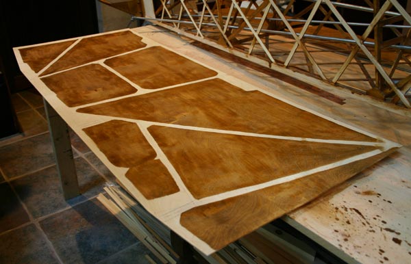
Fit
plywood sides. Had to cut forward pieces a little longer
. Traced position of all longerons and members on the inside
. Drilled small holes at key locations to line up decorative
nails with center of members. Sanded all panels inside
and out.
Varnished
inside of panels except where they will be glued to the
frame. |
Cut,
fit rod ends with rivets and installed final linkage between
front and rear rudder pedals.
Cut,
fit rod ends and install final linkage for right rudder
pedal. |
|
|
8
hrs |
|
|
| 11 |
|
Gave
a second coat of varnish to inside of side panels except
where they are going to be glued to the frame.Gave
2 coats of varnish to outside of side plywood panels.
Sanded
and second coated other side of stabilizer/elevator unit
Attached
side panels with temporary screws and put cowling back
down over their top edge. Cut slots for wing attachment
to rear spar carry thru .
|
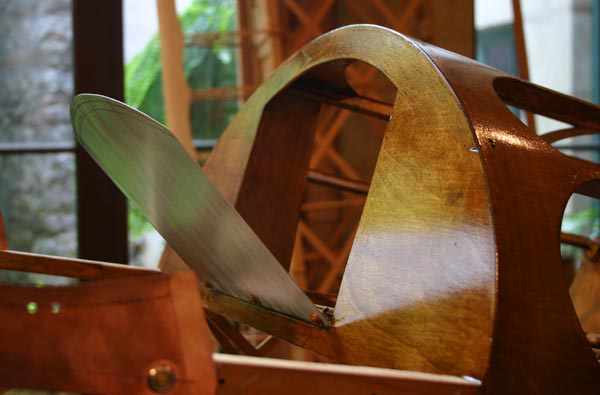
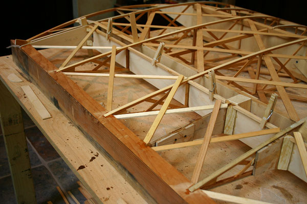
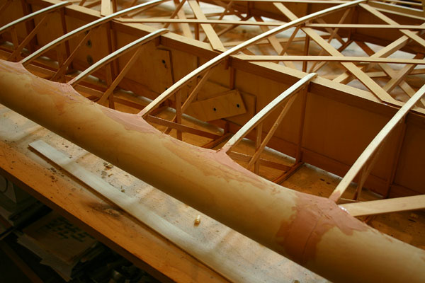
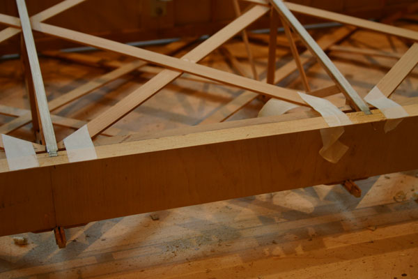
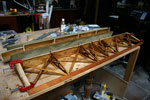
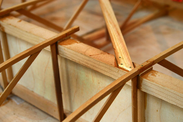
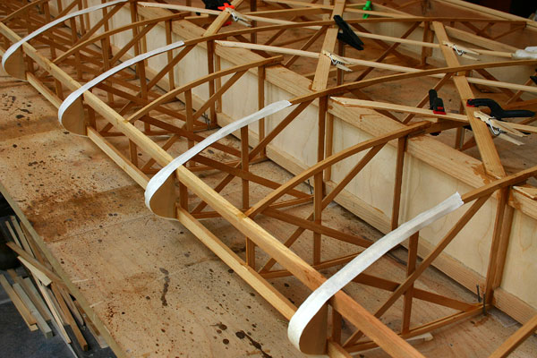
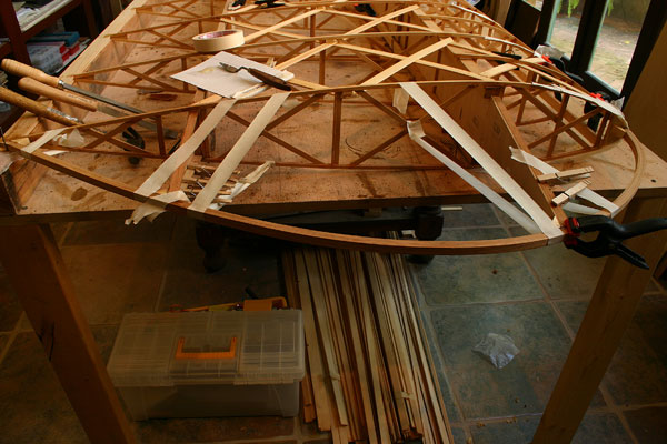
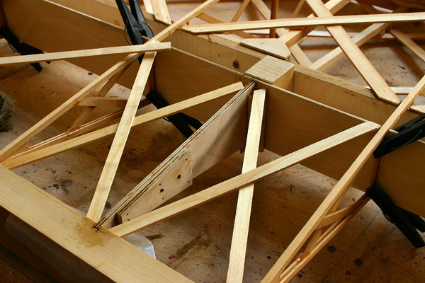
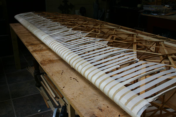
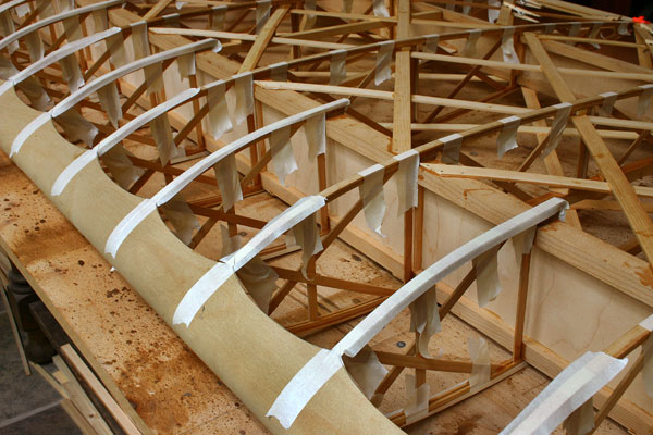
Trimmed
four 3/4"x1/4" stringers down to 1/2"x3/16" to glue to
geodetic in tail section so the fabric touches those instead
of the geodetic . I definitely like the way the light shows
the structure through the clear fabric in the picture,
and that confirms me in my desire to just clear coat the
fabric.
|
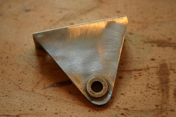
Made
new wider aluminum bracke.t
to replace the heavy steel bracket and attach the trim
lever. Installed the Bowden cable with fittings. Had to
enlarge the hole in the Bowden cable clamp to fit the 7/32"
casing and the hole in the B-nut to fit the .078 cable.
Tried
fitting the trim tab brackets with a B-nut and cable housing
clamp. My only concern is the short travel of the trim
tab lever in the cockpit . I may have to make a taller
bracket to mount to the trim tab to increase the lever
arm and therefore the travel . I could also drill a hole
closer to the axle of the lever in the cockpit. |
|
|
8
hrs |
|
|
 |
I
am going to have to come to a decision about the engine. Looks like
the dream of the HCI Radial may be just a dream, as I can't find
anybody flying one... Considering the enormous cost of and the unproven
design , there is too much of a risk of failure. The Verner firing
only once per rotation gives me concerns about vibrations. The Jabiru
was actually tried on a Classic and did not cut it. The Rotec is
too heavy , and so are the VW conversions. I really don't want a
2 cycle.
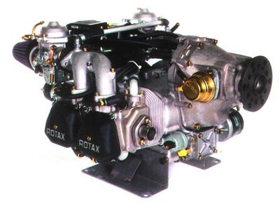
That
pretty much only leaves the 80HP
ROTAX 912UL. It has a proven track record
in many airplanes, the 1500 hours TBO speaks for itself. It is expensive,
but should hold its value well, as there are no used ones to be
found anywhere. I was quoted $11250,
to which one must add the radiator, oil cooler, exhaust kit, engine
mount, etc... Gene is going to get me a price, but has no installation
instructions whatsoever. He has a motor mount design for the Dakota
Hawk that might be used as a departure point to make one for the
Classic.
I
sent an e-mail to Stefan
Wode in Germany to ask hin about his 912
installation. He seems to be the only one that has put a ROTAX
912 on a Classic, and since he just flew it to England, it must
be running pretty good! Hope I can pick his brains...
|
|
|
| 12 |
|
Made
and installed two aluminum backing plates for the third
cabane member. |
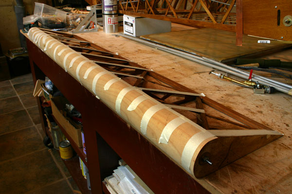
Used
iron to stretch fabric, first at 250F, then to 350F twice
. I used the littlecoiled spring thermometer, which seems
to work fine. Brushed a coat of Poly-Brush on one side,
glued rib tape and 1" pinked tape.
Brushed
a coat of nitrate dope on the other side, then a coat of
butyrate. Polybrush seems best, goes on smoother, doesn't
smell as bad. |
|
|
3
hrs |
|
|
| 13 |
|
Gave
a second coat of Poly-Brush, OUTSIDE !
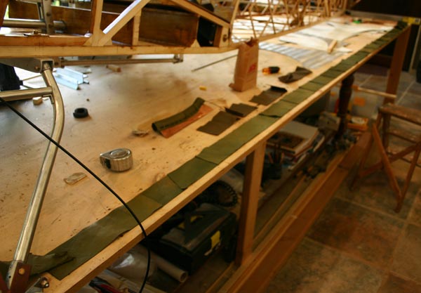
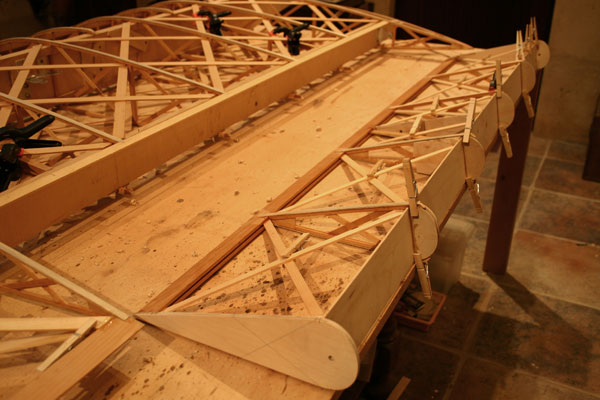
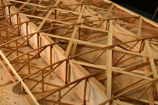
Lined
up stringers on sides of geodetic tail section , and
glued in place , with little spacer blocks where necessary. |
Dave
Melvin came by to look the plane over, and seemed to like
it. He pointed out the pedals were narrow, which I know.
You have to fit two pedals and a seat in 24'',so you either
need very narrow shoes( I looked at driving shoes on the
internet) , or passengers with very small butts! Actually,
preferably both...Also, the bolts on the side of the rudder
pedals tend to catch on the vertical member. We looked
at a way to attach the brakes, either a bracket, or bolts
through the washer welded to the axle. Decided to drill
2 holes , after grinding away part of the lip, and bolt
them.
|
|
|
4
hrs |
|
|
| 14 |
|
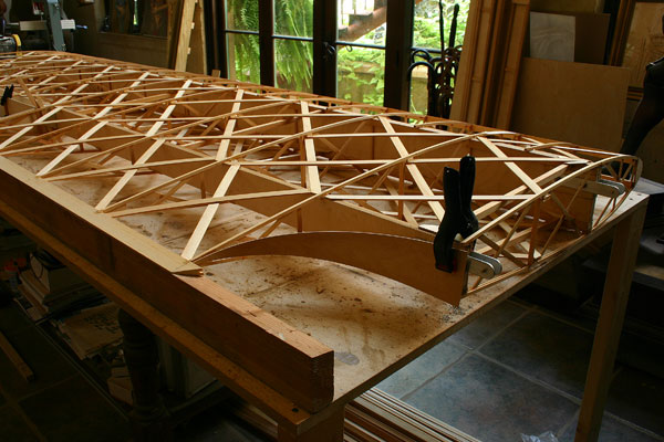
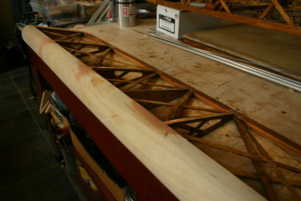
Sanded
stringers and geodetic on tail, and gave a coat of varnish.
I will have to turn the fuselage sideways to do the bottom,
but first need to decide whether I leave it flat as the
sides, or round it, even build a fairing for the control
stick connecting rod that sticks out under the bottom of
the fuselage. I may have to make a turning jig to cover
it anyway.
|
Cut
and installed sheep skin guides for the push/pull tods,
screwed to wood blocks glued to the side of the bulkheads.
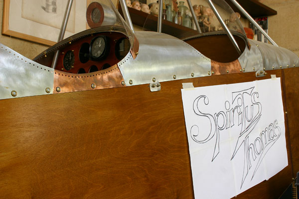
Started
designing the Artwork for the name of the plane: Spirit
of Thomas? Espiritu
Tomas? Spiritus Tomas? |
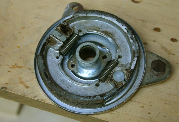
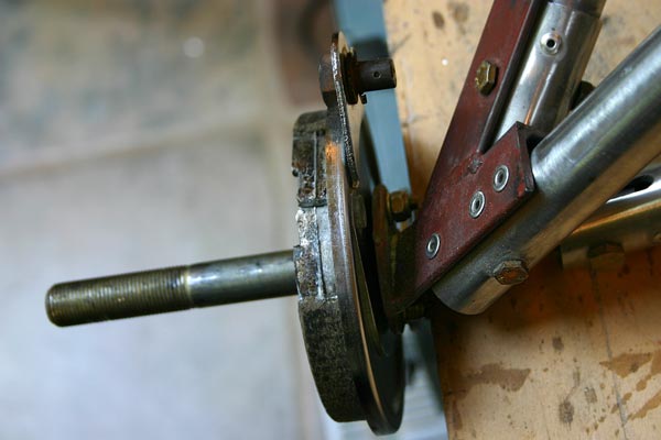
I
called Fisher about thee drums brakes being identical,
and Gene tried to sell me the new hydraulic disk brakes.
I would like them, but that's what I got, and will try
to do with them. Having trouble with the alignment of the
brakes though, that are not well centered with the wheels.
Loosening the screws attaching the drums helps , but I
don't like that much. If I were to go with new wheels and
brakes, I would love some big WW1 spoke wheels, so I did
some research on the net. Not much to be found , except
some nice sturdy 24" ones designed and made by Airdrome
Aeroplanes for WW1 reproductions. The only problem
is they cost about $250 each(not assembled) and also weight
18 lbs each! The wheels I have actually only weight 11
lbs... That would be 14 lbs extra, and would raise the
axles 5". I suppose I could extend the tail wheel
spring down... That would be the right look... |
| Moved
ball bearing on inside of rudder pedal bracket, so bolt head
does not catch on vertical member anymore. I could also replace
it with a clevis fork. |
|
|
5
hrs |
|
|
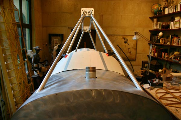
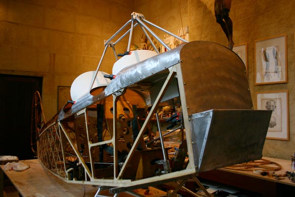
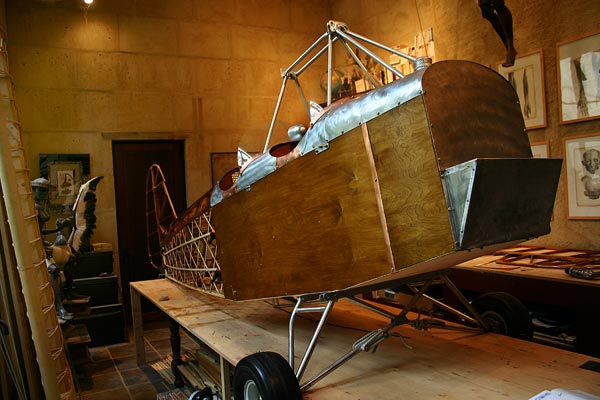
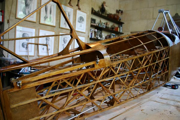
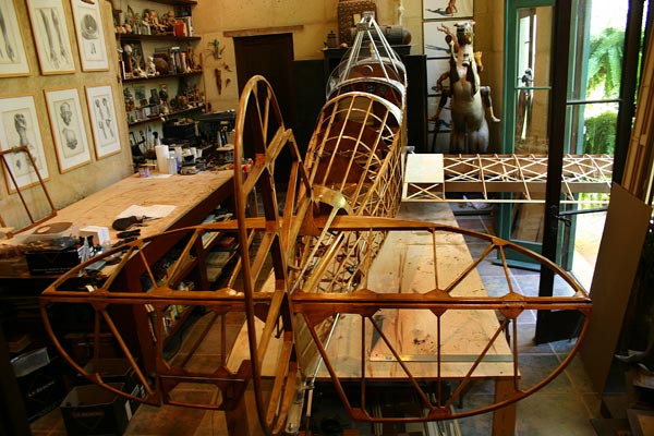
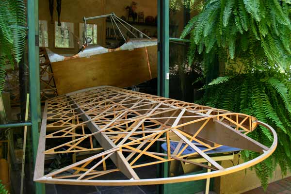
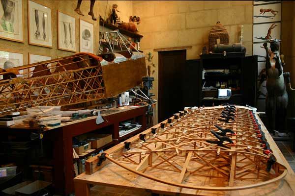
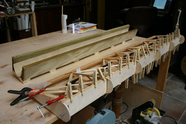
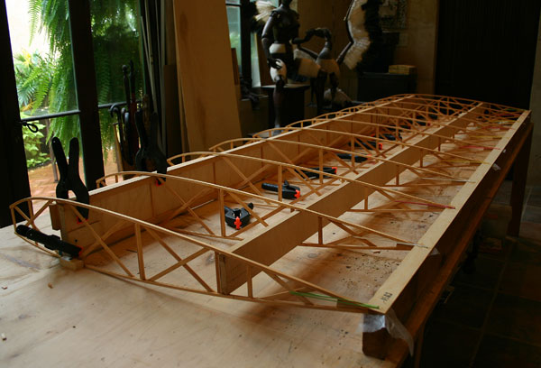
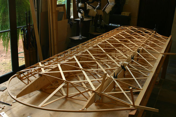
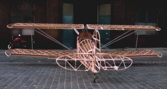
| On
this Sunday 15, I was feeling a little lazy , and just wanted to
see what the airplane looks like with the tail pieces and a wing
on . It is so nice and cool outside I just stuck the wing out the
door...Enjoy the pictures: : |
|
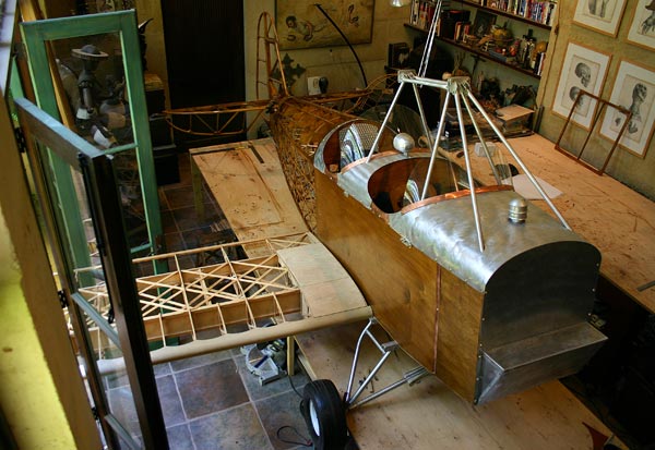
| I
then moved the fuselage over to the other table ,
so I can start working
on the wings. I have already got almost 400 hours in this project
already! |
|
|
| 16 |
|
I
am going to first finish the wing that Tom Hall built,
and make the aileron, before building the remaining 3 wings.
Glued
3/8"x1/16" strips to 1/4"capstrips on the top side of
the wing, to re-enforce the ribs(Fisher now uses 3/8" instead
of 1/4" capstrips), to make plywood leading edge wrap and
wing walk level with ribcaps, and to have a 3/8"wide rib
lacing stitch over 3/8" cotton tape. |
Started
shaping profile of wing tip bow.
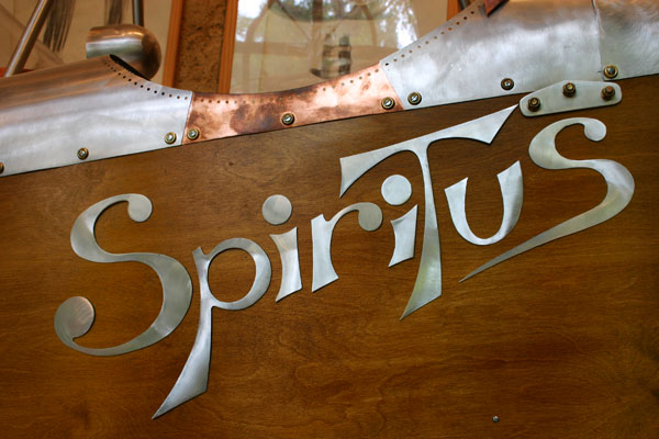
Designed
Artwork for name of plane: the Spiritus Thomas . I will cut it
out of thin aluminum sheet and glue/nail it to the side of
the wood fuselage . |
|
|
4
hrs |
|
|
| 17 |
|
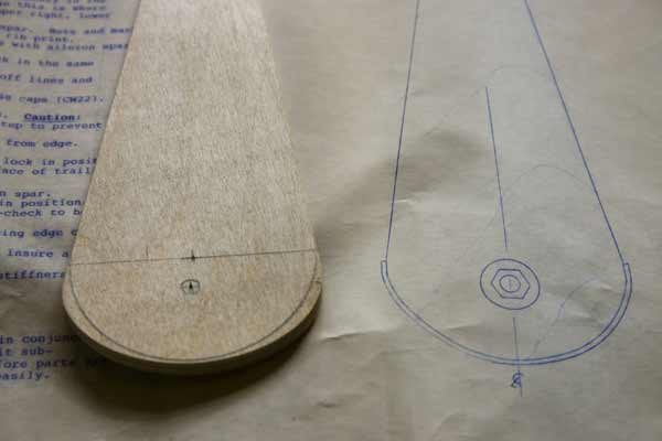
Started
on the aileron this morning, and finding a lot of discrepancies
between the blueprint and the reality. The aileron spar is
not quite wide enough (because the ribs are a little taller
than they should), and if I notch it by the blueprint, it will
be loose. The plywood end ribs for the aileron are on the small
side too, and the leading edge shape is more eliptical , which
diminishes the angle of travel up and down. Should I trim them
into a perfect circle as per blue print.
Also
wondering just how much clearance to leave on each side.
Chuck said 1/4" would be good.
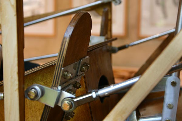
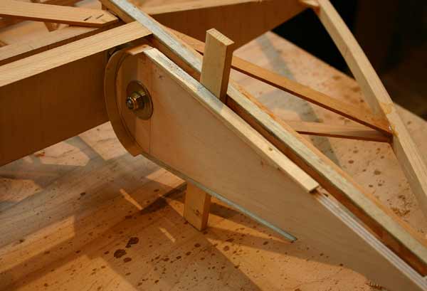
I
went ahead and installed the hinges to see how the aileron
is going to fit and rotate, and what the gap is going to
be as it moves up and down . I cut a temporary
bevelled strip, and bevelled it at a sharper angle and moved
it back and forth until I got the best possible fit. That
gives about 1/4" gap
at neutral,almost no gap on top with aileron up 28 degrees,
and about 1/2" gap on top with aileron down 25 degrees. I
suppose that is satisfactory.
It
seems to me though that the gap could stay about the same
through the rotation if the hinge pin was moved further back
to the center of the circle. But that means the hinge would
have to extend farther and the hole in it be moved back too.
That would require new hinge brackets. I will make it work
with what I got! |
|
4
hrs |
|
|
| 18 |
|
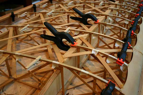
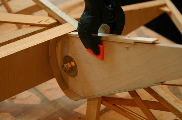
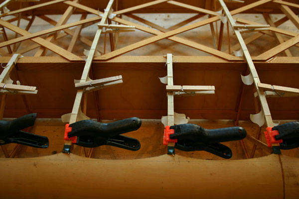
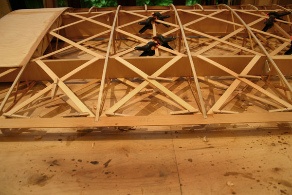
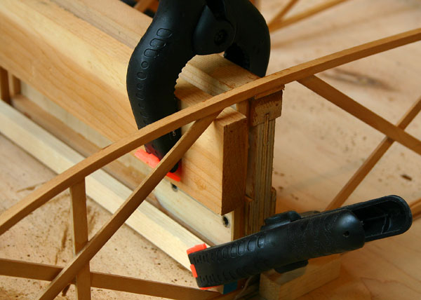
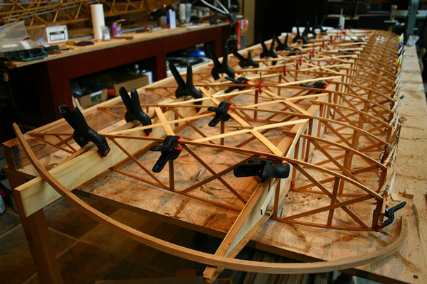
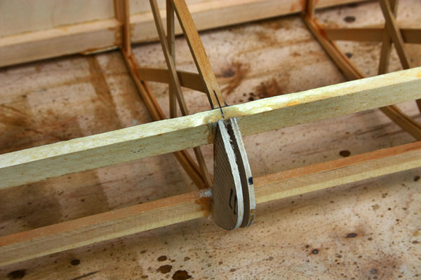
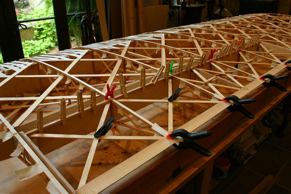
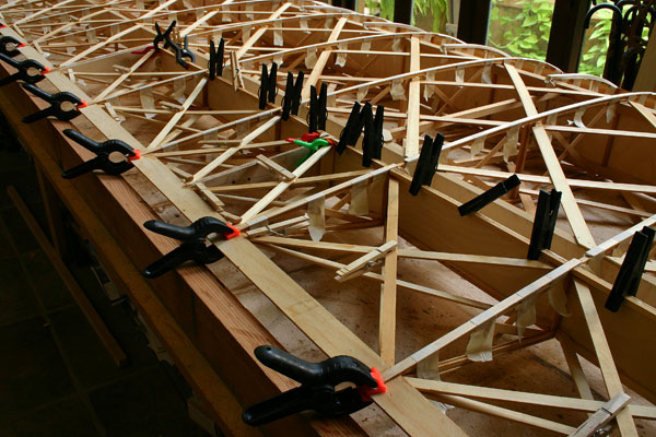
| Cut
and glued 3/8"x1/16" strips on top of the 1/4" rib caps
on the other side of the bottom right wing. As the image
shows, no staples, as they would damage the narrow 1/4"
cap . and leave holes that are a lot of trouble to fill.
Small clamps, clothes pins and 1" masking tape do a better
job. |
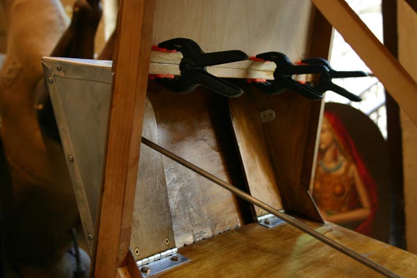
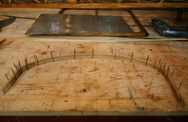
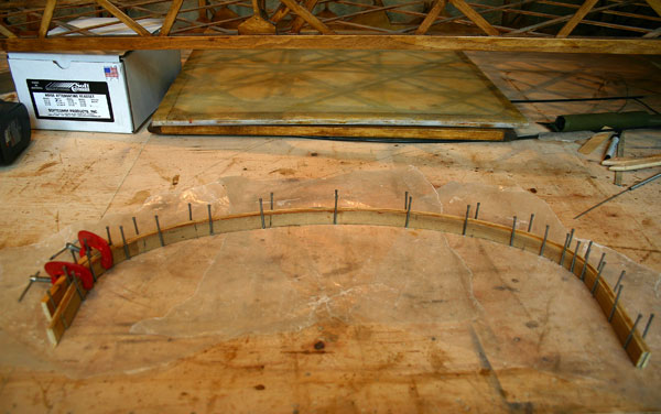
| Bent
three 1/8"x3/4" strips in a nail jig to make an extra laminated
bow to attach to the top part of the flimsy 1/8" firewall
plywood. That will give someting to attach the alumunum
cowling to. I know I could glue the strips wet, but just
would rather let them dry first. |
|
|
4
hrs |
|
|
| 19 |
|
Got
a piece of 1/4" aircraft grade ply from the model shop
and cut 2 new larger end ribs for the aileron, mounted
the hinges, marked holes for pins in place, drilled
and installed pin hinges, glued the aileron spar and
end ribs in place .
While
it dried, I cut all the geodetic pieces and the 1/4"x1/4"
spar caps. |
| Sanded
everything smooth, and spackled leading edge ply with
aero-poxy to get a smooth flow into the rib cap strips. |
|
|
4
hrs |
|
|
| 20 |
|
Cut
new larger nose ribs out of 1/8' ply to match end ribs
and glued them in place.
Fit
and glued geodetic on the bottom side. It is not clear
from the blueprint whether there are 2 layers of geodetic
in aileron, but I will put two..
Cut
aileron off the wing. Notched trailing edge fill strip
to glue to rib ends.
|
Feathered
edges of wing walk.
Spackled
other side of leading edge ply with aero-poxy, as well
as the front and side of wing walk so the curve flows
smoothly into leading edge |
The
blueprint did not show any geodetic in the 3 cells next
to the aileron, so I added some after checking with Fisher.
Also
glued the geodetic to the compression members with
small spacers. |
| The
aileron hinges are a very basic 1/4" steel pin rotating
in an aluminum bracket drilled with a 1/4" hole . I am
concerned the aluminum will wear with time, and asked
Gene about using either a bushing or a ball bearing.
His answer was that they now had a stainless steel hinge.
That is better, and I could use it if it fits the existing
hinge holes in the rear spar. Dick Simpson used rod
end bearings in his Tiger Moth. |
|
|
6
hrs |
|
|
| 21 |
|
Sanded
ends of cut off ribs to fit curve of leading edge.
Cut and glued geodetic on other side of aileron. Glued
1/4"x1/4"
strips on the edge es of the 1/8" plywood aileron
spar , and 1/8"x1' plywood side stiffener.
Made
jig to bend 1/32" plywood for leading edge, wet 2 pieces
and placed them in to dry. |
Sharpened
bevel on the 1/4"x 1" trailing edge strip , cut 1/4"x1/4"
notches, dry fitted , trimmed ends
of ribs some to get proper clearance, and glued it to ends
of ribs and side of ribs at root end and tip end. |
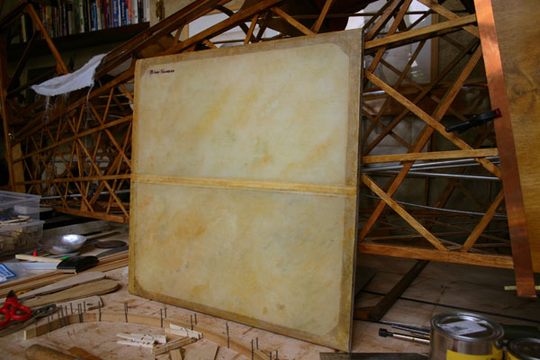
Experimented
with painting/antiquing the fabric panel with a mixture
of Liquin and transparent artist oil paints . It had
been previously given 3 coats of Poly-Brush. Another
coat of or 2 of Polybrush should be enough to protect
it now. |
| Gave
one coat of varnish stain to the bottom side of wing,
the old fashion way, with a little bristle brush... Takes
for ever. |
|
|
8 hrs |
|
|
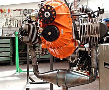 |
An
e-mail from Phil Miller in California is making me reconsider
the VERNER 133MK option. His pointed out that twin BMW
motorcycle engines run very smooth, and that I should not disqualify
the Verner just because it has only 2 cylinders. So I e-mailed
Kim Brown, who according to Gene is putting one on a Dakota
Hawk ,to get his take. His engine is the older 1400, which he
bought used on e-bay, and he has not run it yet. So I e-mailed
the distributor in Florida and am awaiting more info.The Verner
site shows an exhaust configuration that would work. iled
An e-mail from |
|
|
| 23 |
|
| Drilled
hinge bracket hole 3/8" and fitted bronze bushing in. I am a
little concerned about the strength of the aluminum around the
bushing. I would prefer a larger bracket. Gene is suggesting
to get the new all stainless steel hinges. |
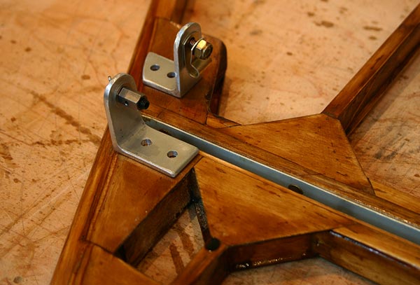
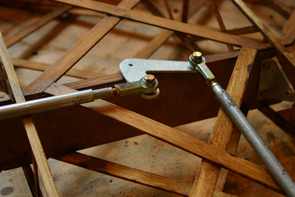
| Fitted
the rod end bearings to the aileron push rods andL shaped lever.
Had to replace the sleeves. The problem I see is that the bearings
fit to the side of the lever and the lever might bind . I may
have to add a second lever to center the forces. |
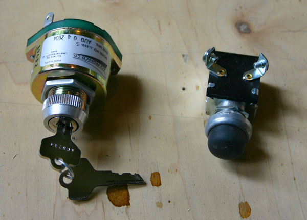
| Got
from Aircraft Spruce a keyed 4 position ignition switch , and
a nice starter button with a rubber cover. |
|
2
hrs |
|
|
| 24 |
|
Varnished
other side of wing and aileron.
Dry
fitted 1/32" plywood leading edge of aileron and marked glue
lines. Varnished inside parts except for glue lines. |
| Laminated
firewall bow. |
|
5
hrs |
|
|
| 25 |
|
Finished
varnishing wing. Gave second coat to inside of aileron leading
edge plywood.
Screwed
beveled 2x4 to table and nailed trailing edge of right
top wing to it. Slid 11 ribs over front spar,and glued
them in trailing edge slots, using rubber bands to hold
them tight. |
| Glued
root rib to main spar against a block screwed to the table
so they are square. There was a 1/8" gap between the top
of the spar and the rib cap that was filled with a small piece
of 1/8" plywood. Even though Chuck said it was not necessary,
I decided to glue the 1/8" thick vertical member of the
ribs to the front of the spar. I want all the strength I can
get. |
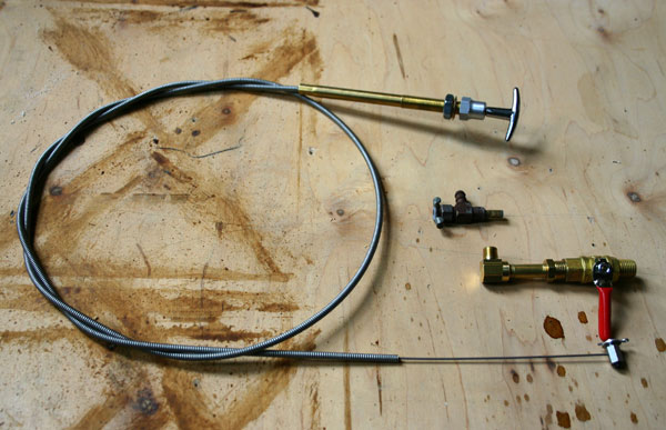
| The
gas valve that came with the kit looks like a small ice maker
line valve ,and being installed just below the tank in front
of the passenger, it would be impossible for a pilot alone
to close it in case of an emergency. I found parts at Lowes
that will allow me to fit a 1/4" NPT ball valve , and
I will modify the lever to control it from the pilot dash with
a T-handle cable . |
|
5
hrs |
|
|
| 26 |
|
Glued
all ribs on main spar. Used 1/8" plywood spacers to fill
gap between top of spar and rib cap, with additional 1/32"
or 1/16' shims.
Slid
in rear spar , and glued ribs to it . Beveled a 1/8" strip
to make little wedges to fill gaps.
Trimmed
half ribs and glued them on. |
Glued
the two 1/4" beveled strips at the front end of the ribs .
Started
cutting and gluing in geodetic. |
|
8 hrs |
|
|
| 27 |
|
Finished
geodetic on top side of wing.
Glued
nose ribs, holding them in place with masking tape. |
Fit
and glued in wing tip bow, after notching first nose rib.
Added 2 blocks at each joint and a flat 1/8"x3/4" strip between
the last rib and the tip.
Cut
a bunch of 1/16"x3/8" strips to cap 1/4"rib caps. |
Glued
1/32" plywood leading edge of aileron . Masking tape worked
great to hold it in place to dry.
Wet
plywood for wing leading edge and put it in the trough to
dry overnight. |
|
8
hrs |
|
|
| 28 |
|
Turned
wing over , cut and glued 4 compression members with gussets,
and geodetic on bottom side of wing.
Started
buildind aileron. Cut 2 new larger end ribs out of 1/4" aircraft
plywood. |
Drilled
rear spar for wing attachment brackets. I should have done it
before on the drill press, but did not realize it had not
been done. Enlarged holes to 3/8" and glued in aluminum sleeves
for 1/4" bolts. Mounted wing attachment brackets to both
spars.
Cut
out end of root rib and part of the trailing edge to allow
for 45 degree cutout in wing and hatch. I would rather make
a larger rounded cut out with 2 layers of laminated 1/16"
plywood and may be dispense with the hatch altogether. It would
look better than that straight cut . |
Blew
up the design for the name on the computer and taped it to
the side of the fuselage to see how it would look . That
would be cut out of thin aluminum flashing material , glued,
and nailed with small brass or copper nails to the plywood
side . I might spell Thomas with no h as latin Tomas instead.
|
|
8
hrs |
|
|
| 29 |
|
Installed
hinges to build aileron, cut trailing edge to fit end
ribs, notched aileron spar and glued it in place with blocks.
Drilled end ribs for hinge pins and glued them to spar and
trailing edge.
Cut
and planed a bunch of 1/8"x1/2" strips out of larger stock
and cut geodetic for bottom side of aileron. |
Notched
front of trailing edge piece 1/4" and glued in the extra
plywood rib and doubler to attach aileron horn at midway
point of aileron.
|
Added
two extra 1/8" ply nose ribs were the 48" sections
of skin meet . Cut 1/32" plywood skin sections to fit . Taped
leading edge skins to the front ribs and marked the glue
lines on the back side. |
|
6
hrs |
|
|
| 30 |
|
Sanded
nose ribs for smooth transition to rib cap. Glued nose skin
sections in place and held them tight with a lot of strips
of 1"masking tape. I would rather do that than shoot staples,
which are more destructive, and then have to be pulled, and
leave holes that are a pain in the butt to fill.
|
Glued
aileron 1/4"x1/4" spar cap strips, and geodetic pieces on
the bottom side.
Glued
aileron nose ribs after cutting new ones out of 1/8" plywood.
|
Glued
the 1/16"x3/8" strips on top of the 1/4" rib caps. Taped
those on too instead of stapling.
Talked
to Gene about a round top wing opening instead of the 45
degree cut and no hatch, and he is OK with it. Cut a piece
of 1/8" ply to make curve. |
|
8
hrs |
|
|
| 30 |
|
Glued
more of geodetic on top side , as well as aileron spar cap
pieces. |
Glued
1/16"x3/8" strips on rib caps on top side of wing. Marked
scallops using Tom Hall's template, and cut them with a sharp
knife.
|
Sanded
and spackled lower right aileron leading edge and ribs.
|
| Cut
out an S out of the thin aluminum flashing and realized it
was too flimsy, so I cut the letters out of .035 thick cowling
scraps . They look nice, but I will need more aluminum. |
|
8
hrs |
|
|
| TOTAL 475
hrs |
|
|