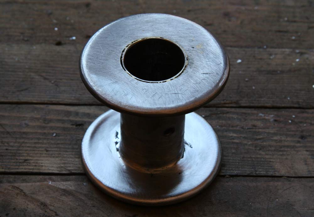
To finish the landing gear, I had to weld the flanges on the aluminum shock cord spools. I ordered that expensive HTS-2000 brazing rod from the Internet( http://www.aluminumrepair.com/ ) , hoping it was easier to use than the cheap ones I tried before , but it wasn't. Heating the metal with a propane torch takes for ever, and the oxyacetylene torch tends to melt it. I finally manage to get it somwhat under control, but aluminum is such a good conductor that when I tried to braze the second flange on, the first one fell off!
I wanted a better way to weld aluminum for the future Baby Bugatti project, so I decided to get the $100 MIG kit for my little LINCOLM WELDPAK 100 wirewelder and a 20 cu.ft bottle of pure Argon for $70. At first, it was awful, I couldn't do anything but make big aluminum beads sitting on the surface. A whole day and a bottle of Argon later, after wasting a lot of wire and 1/8" aluminum plate, I had it sort of figured out. Four things are key. First, any trace of aluminum oxyde has to be brushed or sanded off for the weld to penetrate . Second, a lot of voltage is needed, I maxed out the machine at setting . Third, you have to move fast and feed the wire very fast, with the speed maxed out at 5 too. Fourth, he aluminum wire is very soft, and tends to tangle up at the feeding wheel at the slightest resistance, so you have to keep the feeding tube as straight as possible to limit the friction. But then it still gets tangled up for no apparent reason. I went to the Lincoln Electric web site, and found they recommended a kit K664-2 with a teflon wire feed tube and a wheel with a round groove instead of the standard V groove that crushes the soft aluminum wire. I ordered it. As far as the Argon is concerned, if you want to be cheap( the 20 cu.ft refill is $16)and keep the flow slow, the tip has to be so close that you don't see the puddle, and the wire tends to melt back into the tip . I ended up turning it up quite a bit, and holding the tip about 1" from the surface. At first, it was easier pulling the tip to the right ,away from the puddle . But Lincoln recommends feeding it into the puddle to the left, and with a little practice, I did get a cleaner weld that way. Still, it is not easy. You can tell its going right from the bacon frying sound.
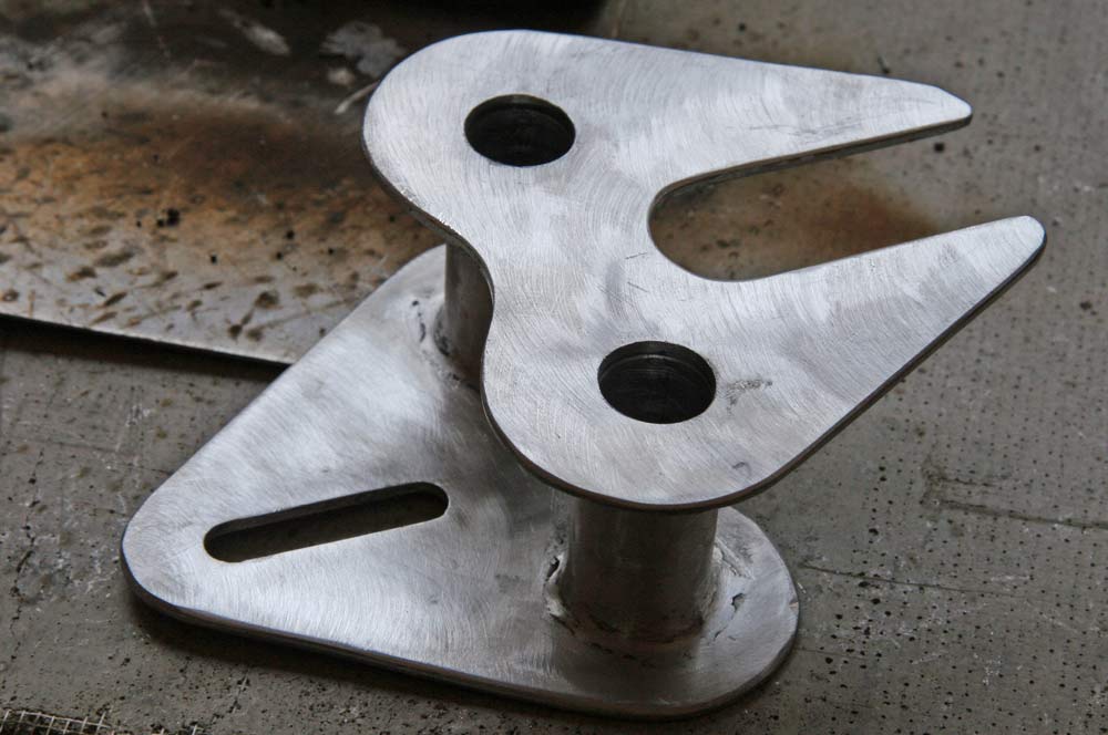 |
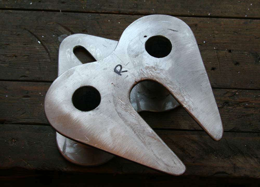
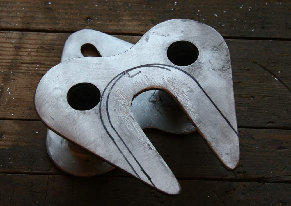
After all that practice experimenting with aluminum brazing and welding, I finally bit the bullet and welded the flanges on the shock cord spools. It didn't look too god, but filed down OK. Those welds are not stuctural anyhow, all they do is keep the shock cords lined up. I will need a lot more practice to make perfect weld... | 3 hrs |
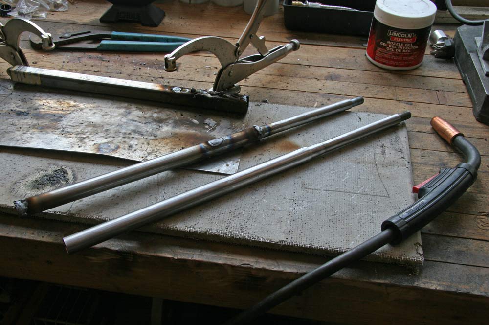 |
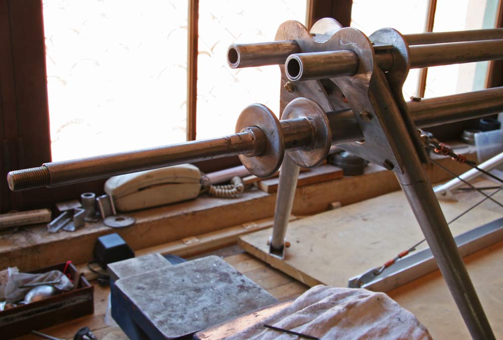
I then welded the tubes that constitute the axle inside one another and ground the welds smooth. | 3 hrs |
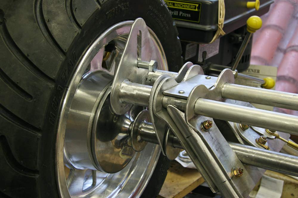 |
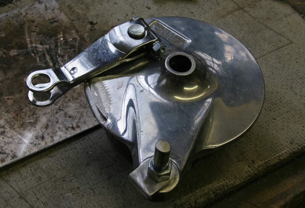
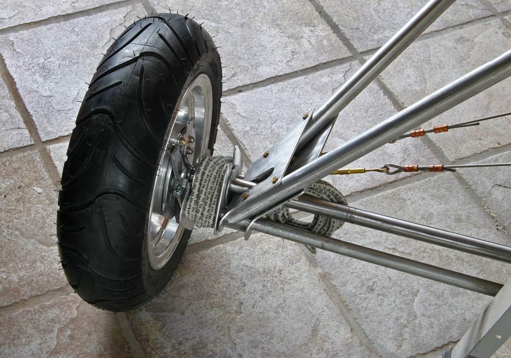
Here is a picture of the final assembly, with the bolt that keeps the brake from rotating and allow vertical movement. | 4 hrs |
 |
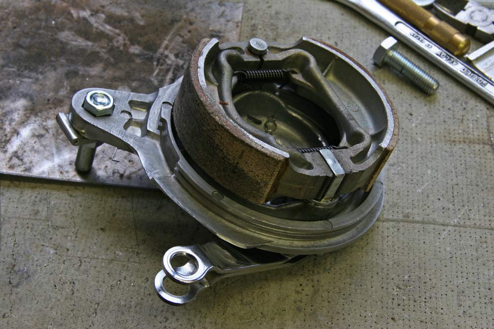
The brakes cable guides must be attached to that bolt , and the lever turned upside down to line up with it. I had to grind some of the edge of the hub for clearance. | 1 hr |
 |
I cut a side of a piece of corner aluminum and drilled a 1/16" hole for the cable. | 1 hr |
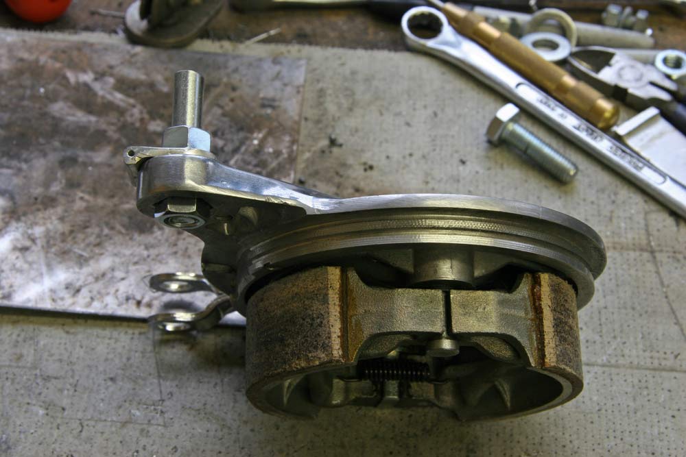 |
I ground the hub bracket and drilled a 3/8" mounting hole in the wire guide so it would not rotate and stay lined up with the end of the lever. | 1 hr |
 |
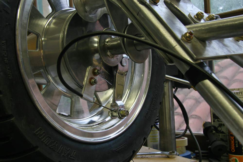
Unfortunately, that won't work. I realised when I tried to route the brake cable that I would have a loop too close to the ground, that might cath on something on a grass landing strip. Back to the drawing board! | 1 hr |
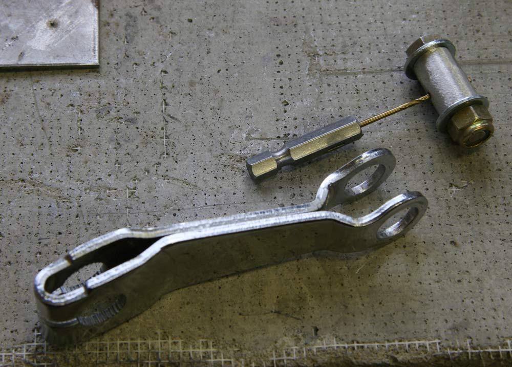 |
First, I made a rotating attachment hub for the ball end of the cable, to fit the rather large holes in the brake lever . That was an assembly of two aluminum tubing sections on an AN-4 bolt with washers, that were drilled as a unit with a 3/32" hole for the cable. | 1 hrs |
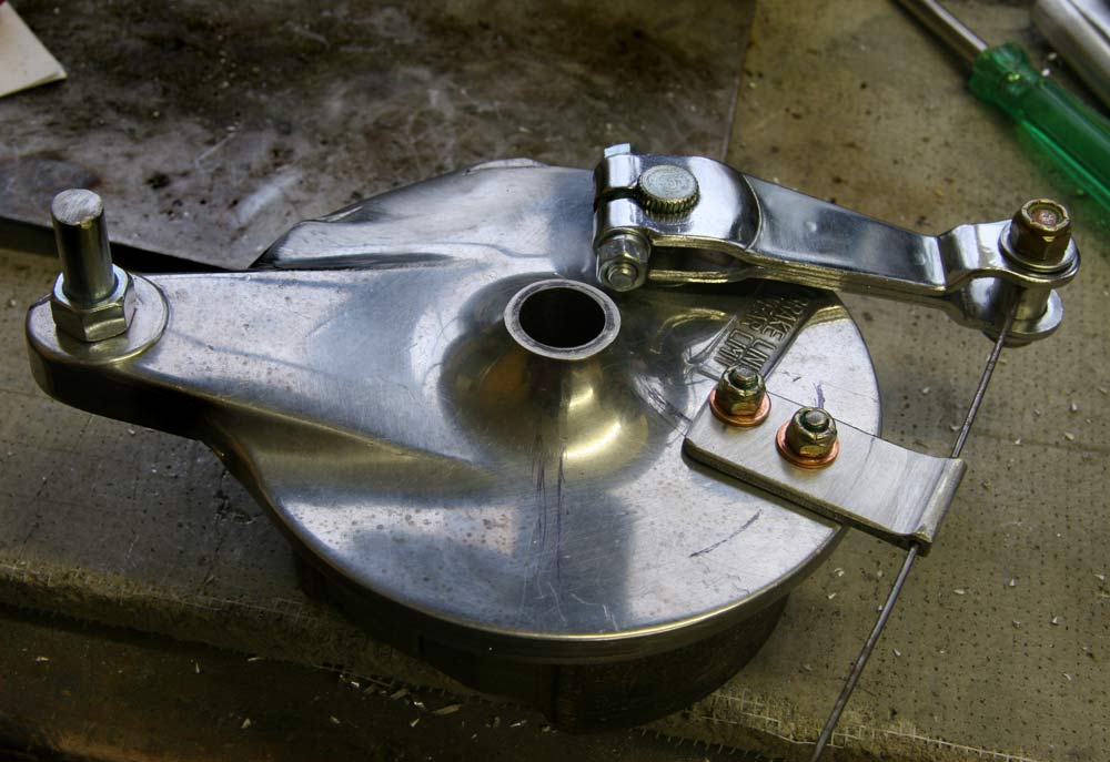 |
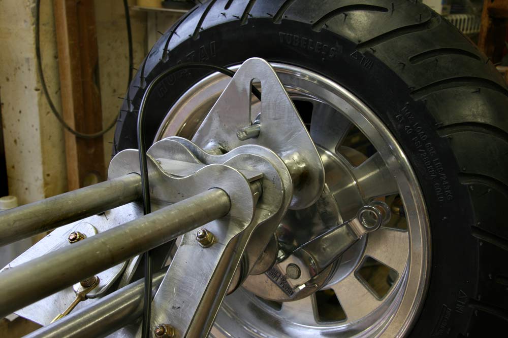
I reversed the brake lever and made a new bracket out of a 1 1/2" x 2" piece of angle aluminum . I drilled a 3/32" hole in the corner and cut the extra "wing" as before. I drilled 2 holes in the brake hub to bolt it on with AN-3 bolts, using a piece of piano wire to make sure the hole in the bracket lined up with the cable attachment hole. |
1 hrs |
 |
That did it, the brake cable loop is now above the axle. |
1 hrs |
 |
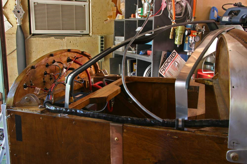 |
I added the wires for the CHT gauges , and tape all the wires out of the panel into a harness with black electrician tape, and ran it on top of the longeron to the front of the fuselage. |
1 hrs |
 |
The firewall was drilled and rubber grommets fitted to get the wires into the engine bay. |
2 hrs |
 |
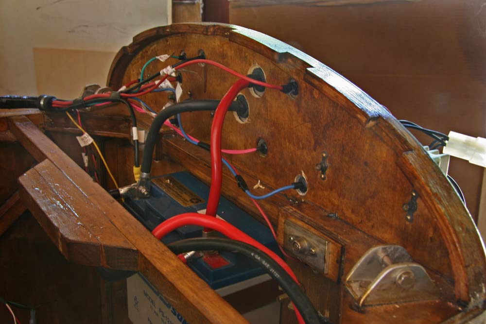 |
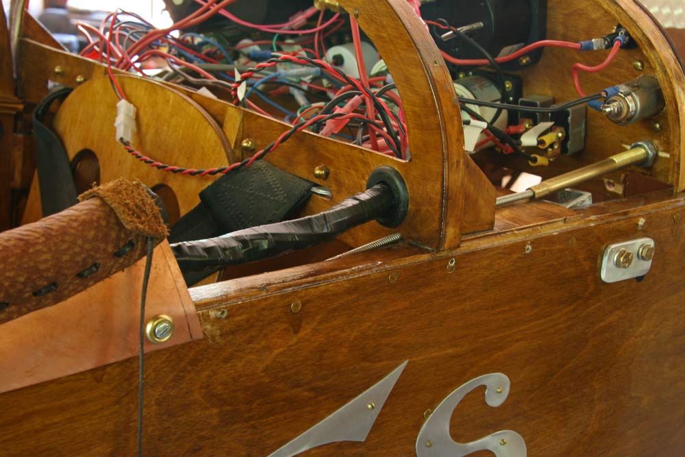
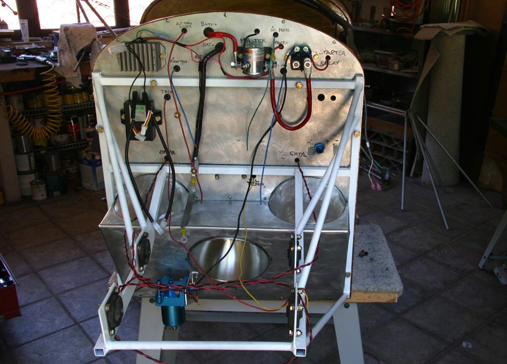
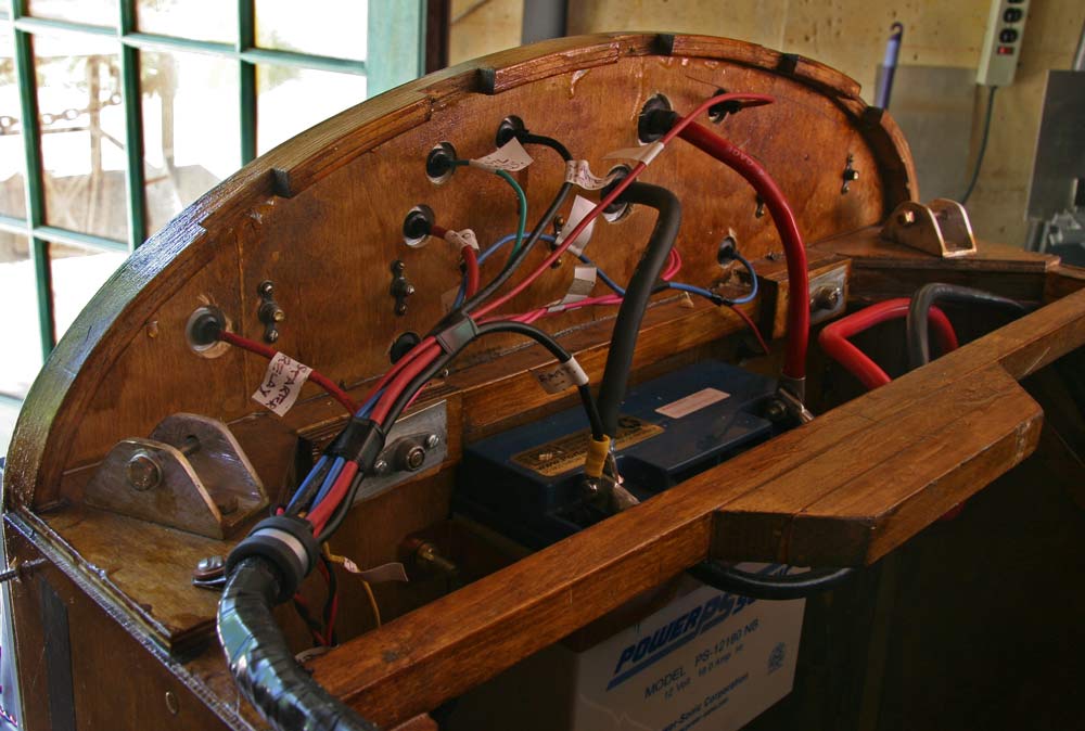
These are two views of the back of the firewall, with all the wires taped and labeled. |
1 hrs |
 |
I wrapped the bungee cord around the spools as many turns as I could and tied it temporarily. | 1hrs |
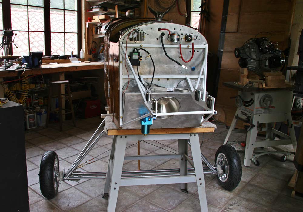 |
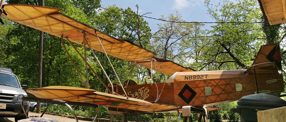
I placed the gear under the fuselage, for the first time actually. It does looks good, but how is it going to hold up in tests... | 1hrs |
 |
I reset up the test rig, applying the weight to the axle just next to the shock cord, and realised soon the shock cord was not tight enough, so I tightened it and added a couple of turns. Well , the gear does hold about 1600 lbs in this picture, but the axle bends a little too much... I will have to increase its diameter, to either 1" or 1 1/8". I want it to bend a lot less, so I finally decided to order a piece of tubing with a 7/8" ID a 1/4"OD, even though it will add about 6.5 lbs to the weight of the gear. |
2hrs |
 |
The new axle came from Aircraft Spruce overnight, and I cut the ends of the old one and fitted them inside the OD 1 1/8" x 1/8" wall pipe. I kept the old spool, and simply secured the ends with two AN3 bolts instead of welding. |
2hrs |
 |
 |
 |
The aluminum plates were already quite scratched up just with the test, so I ground a curve on the inside of the spool and gave it a smooth polish. If this is not sufficient, I will add a 1/32" teflon liner. |
1hrs |
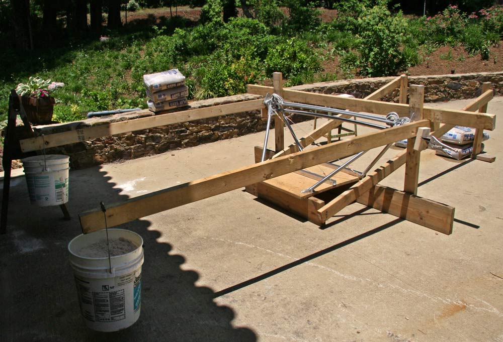 |
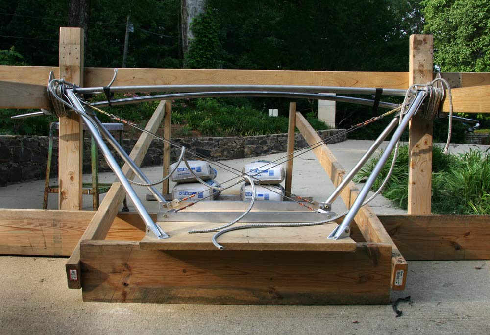
I set up the test rig again, and put up to 2000 lbs on the gear. The buckets of sand are 60 lbs, and the lever arm about 17. That is 2.5 G's on a 800 lbs gross weight. The new axle does still bend under the 2000 lbs load, but a lot less than the previous 7/8" one. But the shock cord ran out at a load of 600 lbs, which is not sufficient. I will rewind it tighter. I called Gene at Fisher to ask how much weight they had tested the standard Classic gear at, but it appears they actually never tested it. I hope Mike Fisher did back when he designed the plane... Anyhow, he thought that was sufficient. |
2hrs |
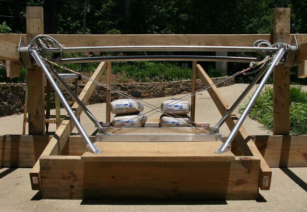 |
So I rewound the shock cords tighter and added a few turns, then retested it. They now gets half way down the slot at 800 lbs, which seems a good compromise, and should provide sufficient shock absorbing down a moderately rough runway. I did put briefly my full 180 lbs on the end of the 2x4 levers just to see, and that raised the test load to more than 3000 lbs. The gear held up. The bending axle acts as a shock absorber. That ought to be sufficient for a pretty rough landing! |
2hrs |
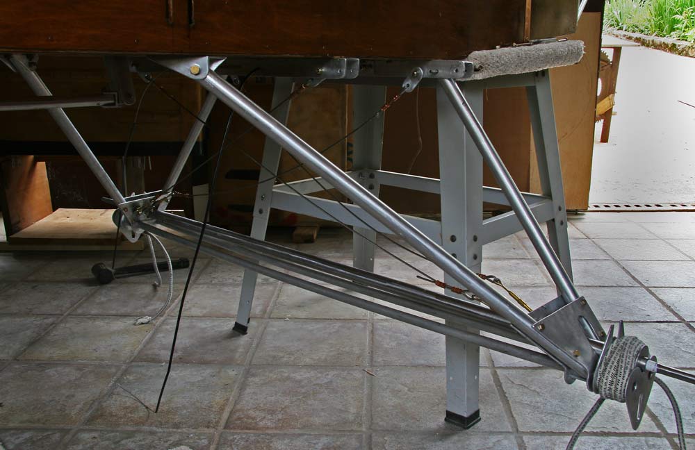 |
I drilled the holes in the front spar carry through to attach the rear legs of the gear with 4 1/8" AN3 bolts. I attached the front legs to the front aluminum channel, and the rear to the spar carry through. |
2hrs |
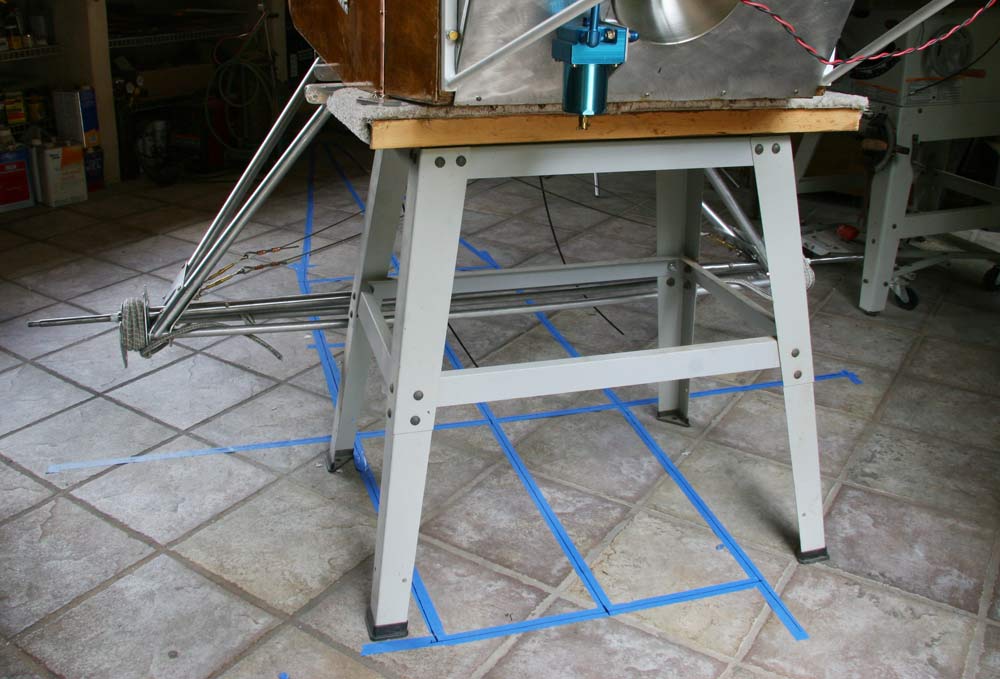 |
I leveled the plane and used a level to drop reference points and draw the fuselage and the axle on the floor . The axle is perfectly square and level, and all measurements are well within an 1/8 " . |
2hrs |
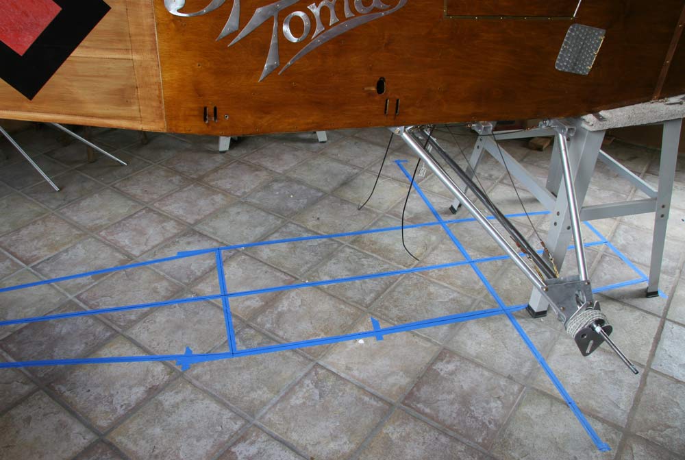 |
also measured from the ends of the axles to the bottom rudder attachment bolts on the tail post , and that was also well within 1/8". Once confident everything was right, I then drilled the holes in the bottom longerons for the second bolt of the rear gear leg attachment bracket and bolted the gear on for good. I |
1hrs |
 |
 |
 |
 |
 |
16 hrs |
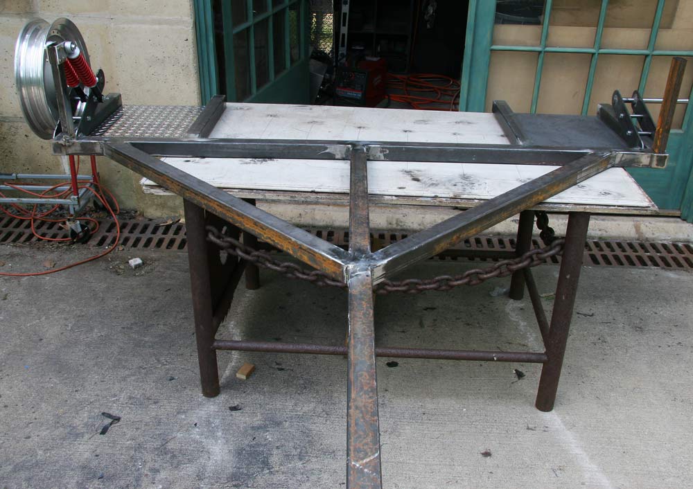
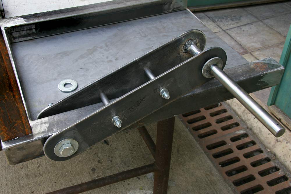
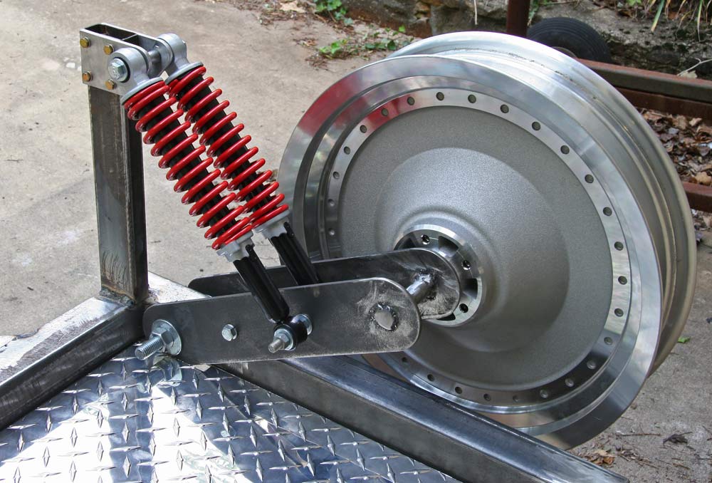
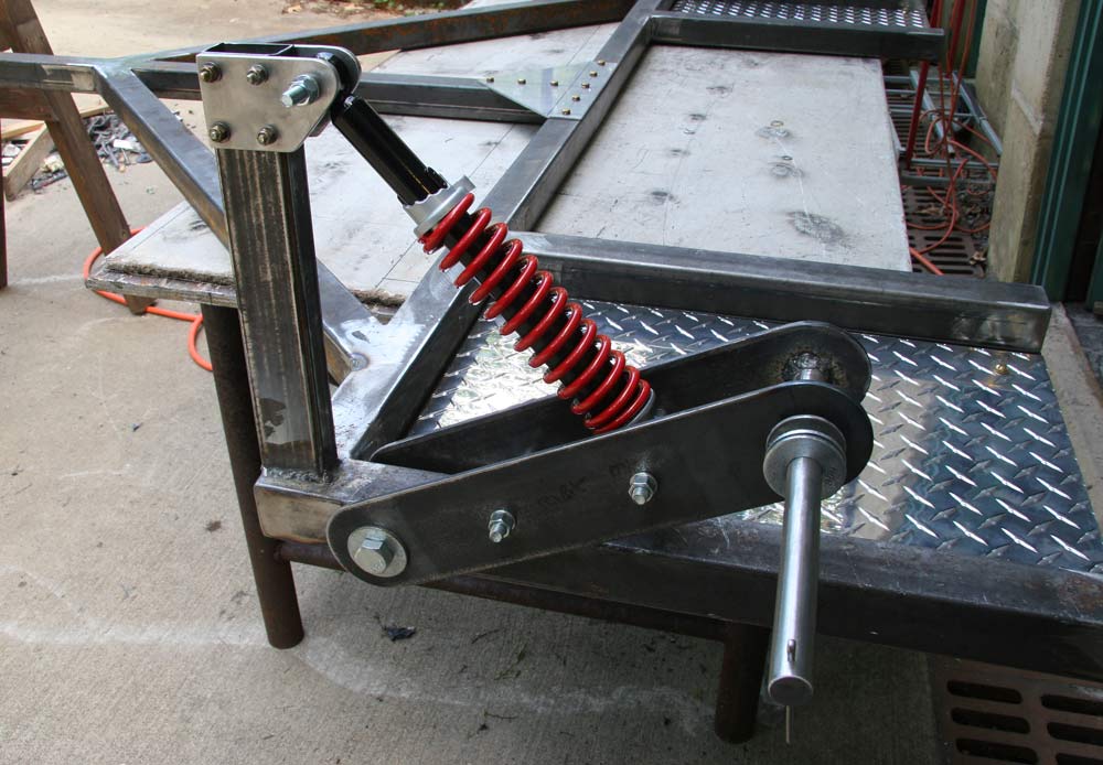
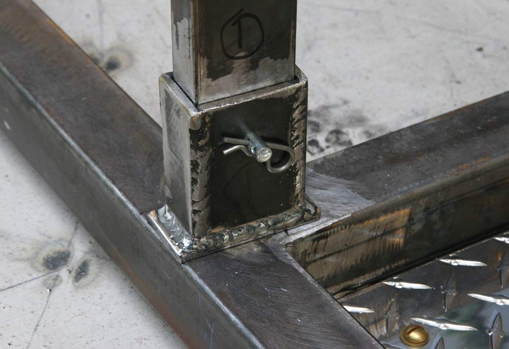
I cut all the pieces to length first with the chop saw, cleaned up the burrs and sanded the areas to be welded. I made the 4 suspension arms out of 3" x 3/16 " thick steel flat bar. They were all drilled together so the holes would match perfectly, increasing bit size from 1/4" to 3/8", 1/2', 5/8' and 3/4" as needed. The wheels axles are solid 3/4" steel rod, and are welded to the swing arms. The arm pivots are 5/8" bolts. The axles are drilled with 1/8" holes near the end for pins to keep the wheel in place. All the tubing is welded together, the ends capped with 2x2 squares.
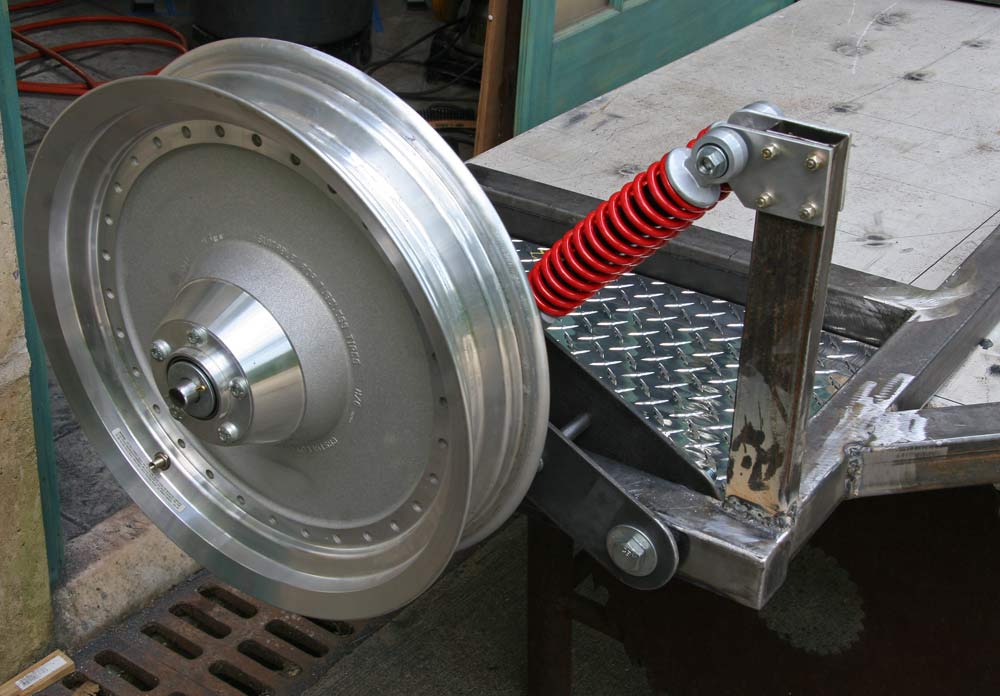
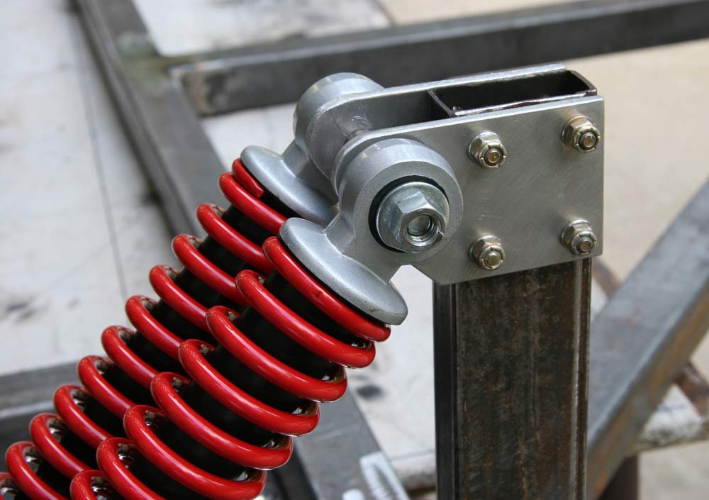
The pair of go kart shocks are attached to a welded 1" x 2 " steel post with a pair of 1/4" aluminum brackets bolted to the post with four AN3 bolt. I want the frame to ride close to the ground, about 6", and want to limit the travel of the suspension arms to no more than 4" . I am just guessing 2 will be better than one... There is a 2 to 3 lever arm, and they came as a set of 4 anyway!
 |
 |
 |
 |
 |
8hrs |
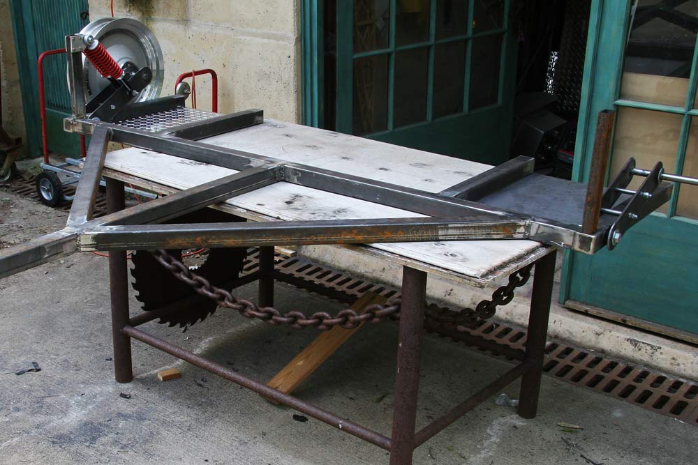
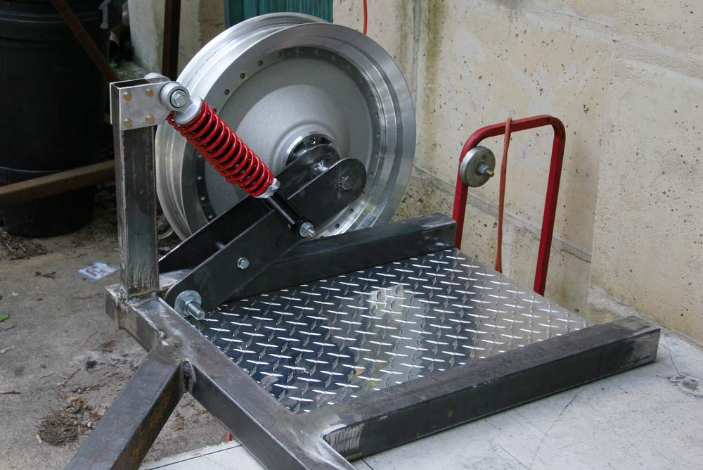
The aluminum tread plates are not structural, as 1/8" steel plates are welded to the frame on each side to form a pad for each wheel of the plane.
My second Harley wheel was fitted with conical bearings, so I removed them and aII ordered regular radial bearings to replace them .
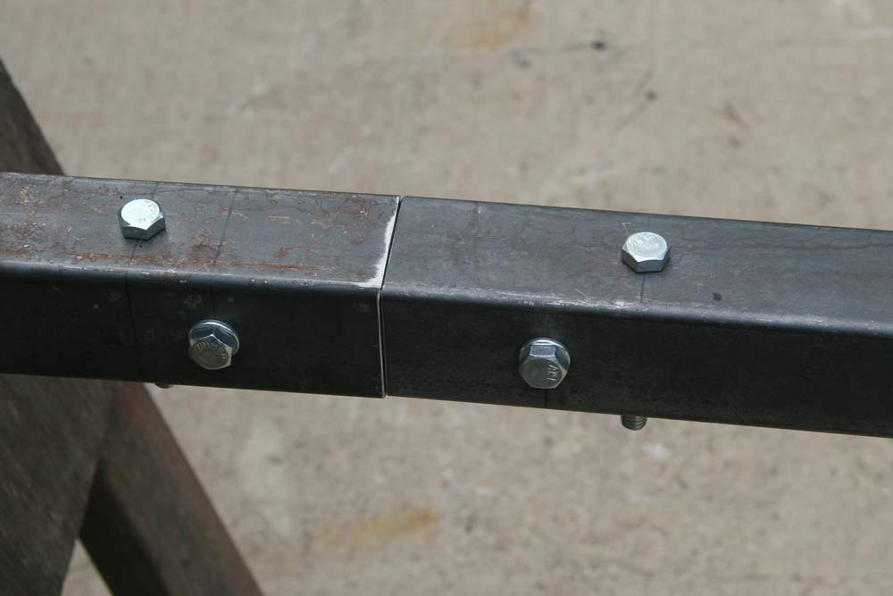
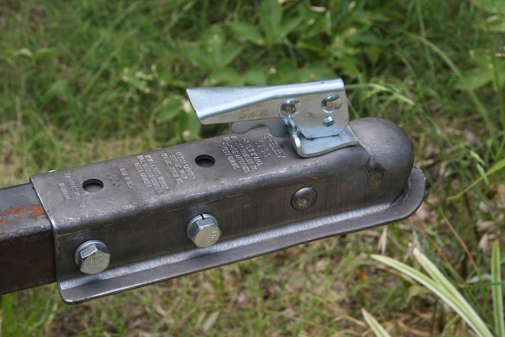
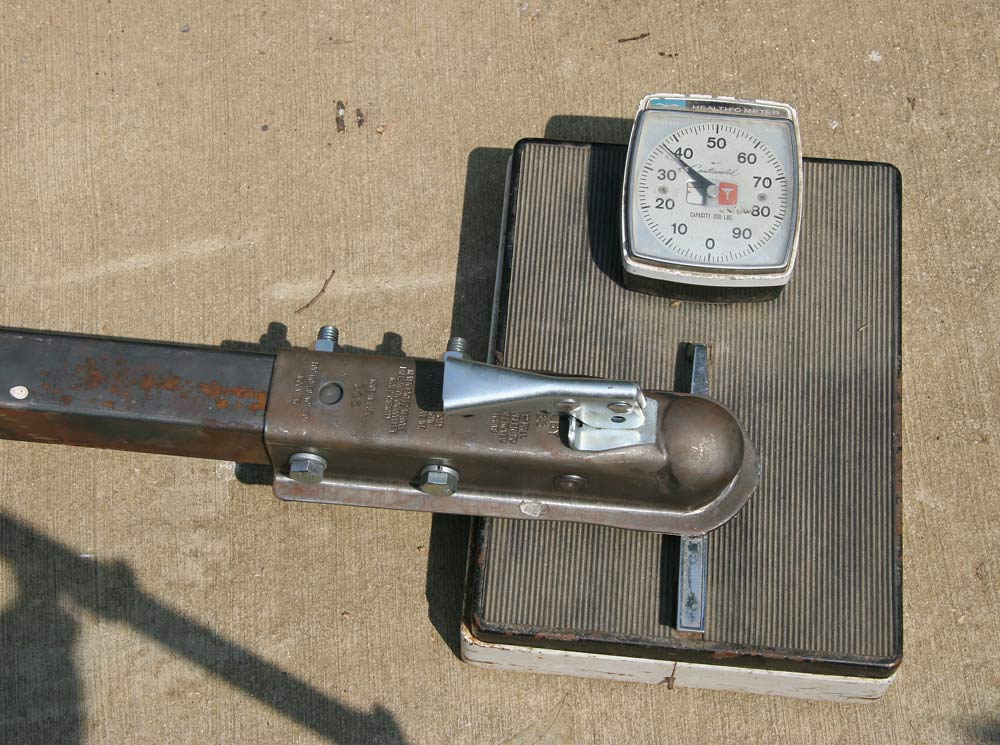
I put only one shock on the left side, and will see with tests whether I need one or two in the end. I made a connector for the long section of the T using two pieces of angle iron cut and welded together to fit inside the 2" x2" square tubing of the frame, and bolted the two pieces together. I bolted a trailor connector with a 2" ball receptacle on the front end. Now, I need to get a hitch on the car.
 |
 |
 |
 |
 |
16hrs |
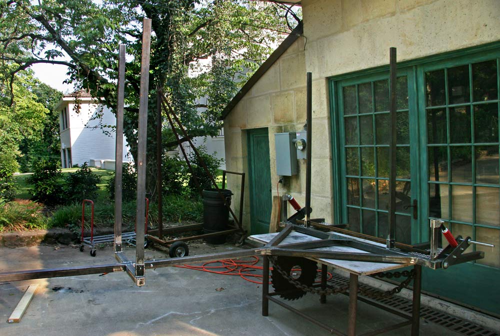
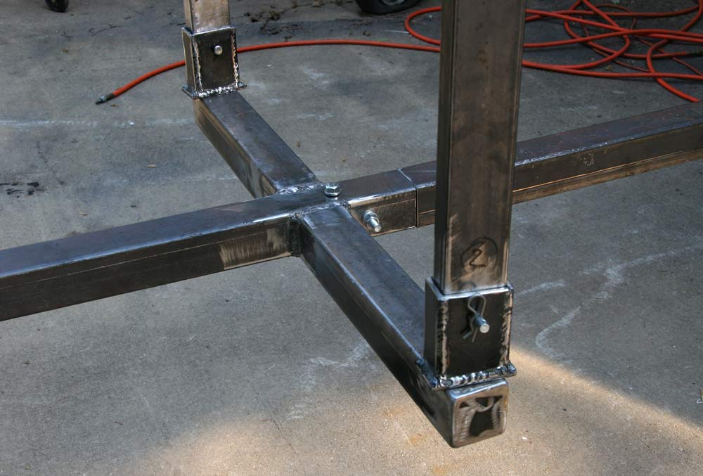
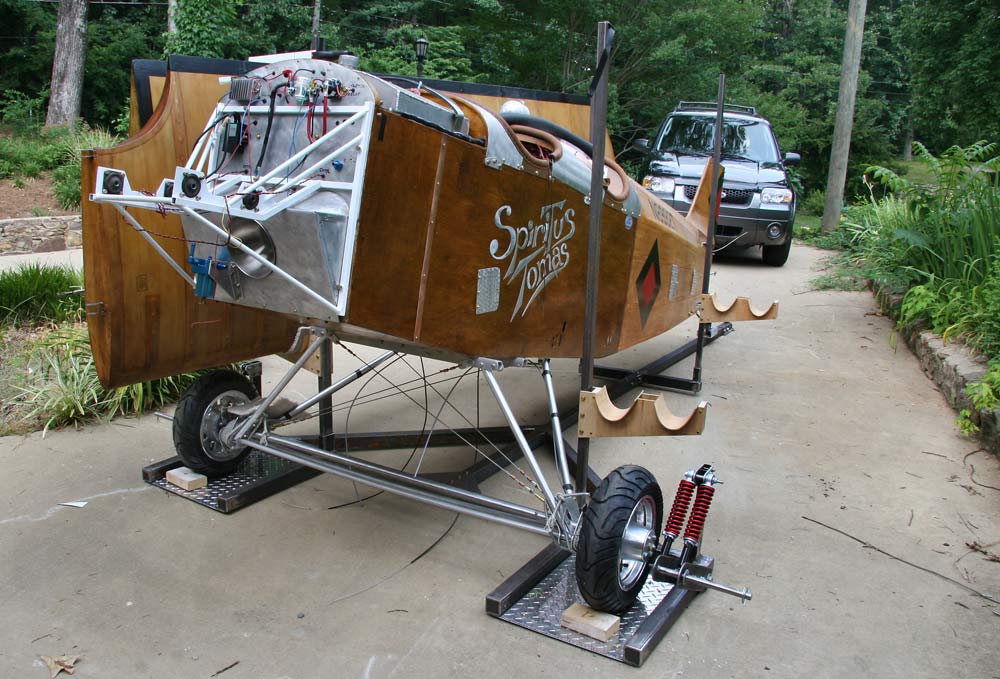
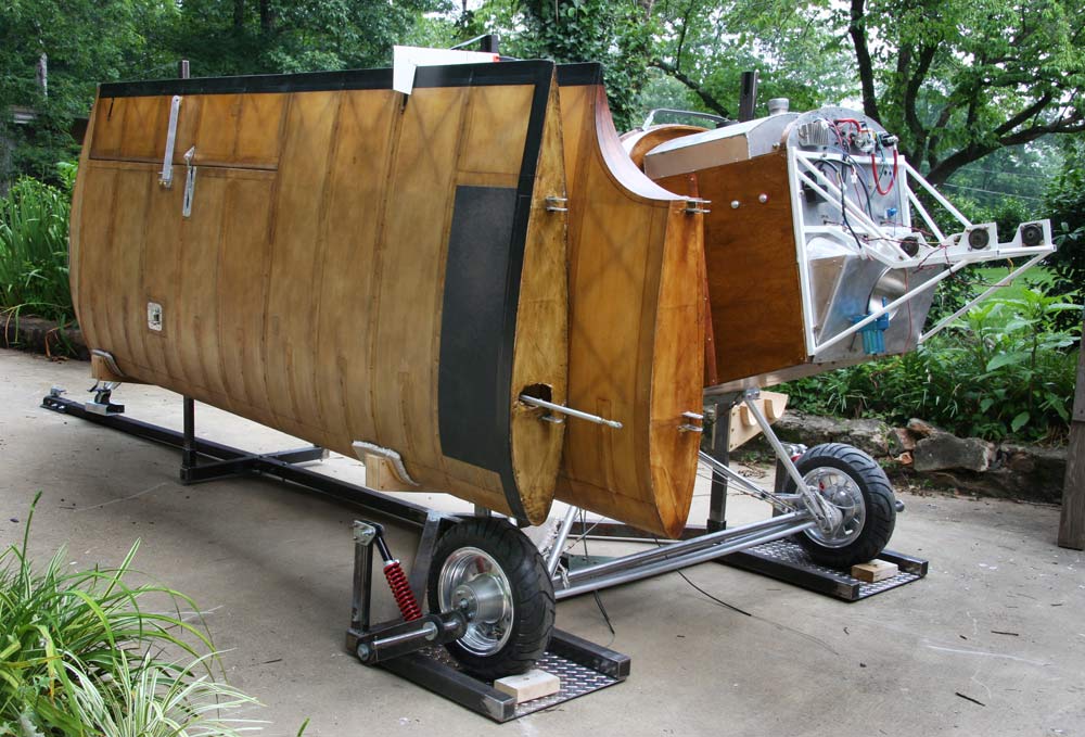
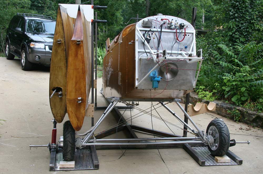
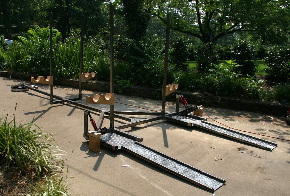
I welded the two supports for the vertical wing posts, and spent pretty much a day making the 4 posts the wings are going to hang on out of 1" x 2" thin wall steel, and the 4 receptacles for the posts out of 3/16" flat bar. Getting the fit was time consuming
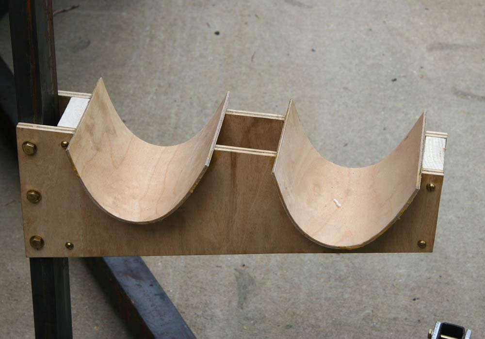
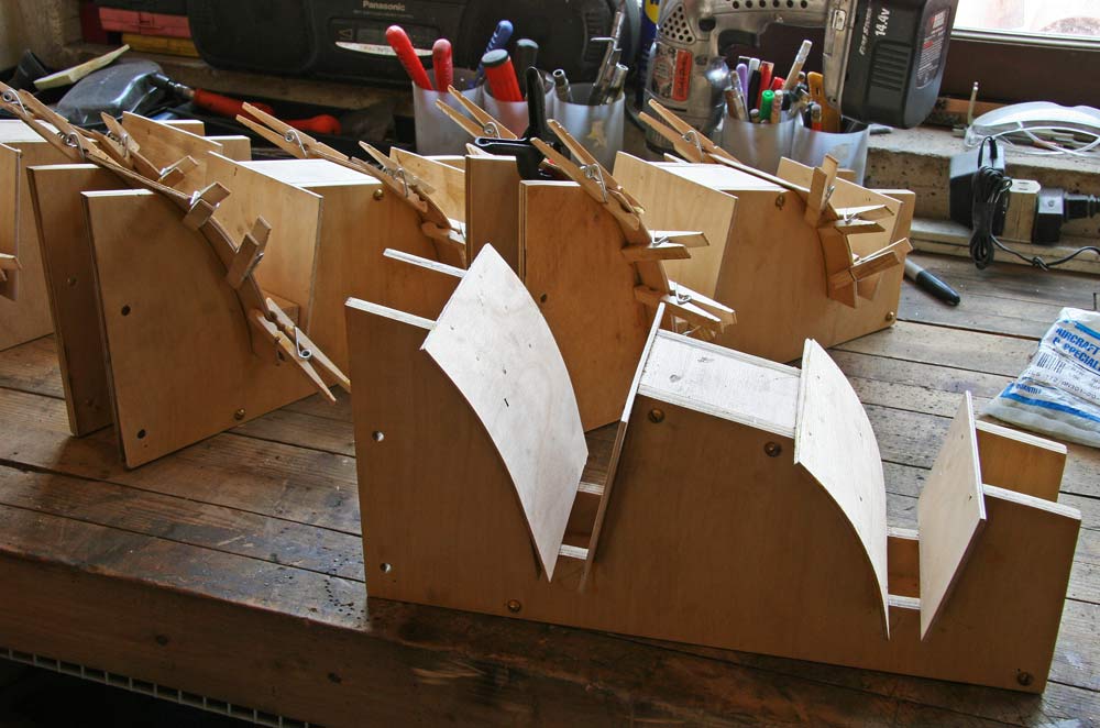
I then made 4 plywood brackets with curved pads matching the leading edge curve , allowing for a 1/2" piece of foam padding. They bolt to the posts 18" from the bottom to support the wings. I took the plane out to try them and determine the shape and size of the top brackets.
 |
 |
 |
 |
 |
8hrs |
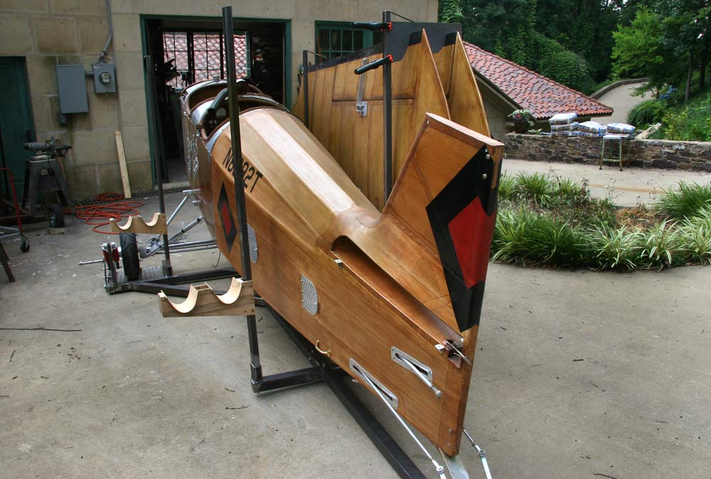
I made a support for the tail wheel out of a 2" x 4 " section of rectangular aluminum tubing. It is notched in the top to allow the tail wheel to roll in , and there id another notch the axle bolt drops in to hold it there.
I used pieces of carpet to temporarily pad the supports, and cut out a cardboard pattern for the top bracket. I want to be able to lift it to free the trailing edge of outer wing while still holding the inner wing in place. The rotation point is determined by trial and error as marked, and curves have to be cut on the inside to allow the rotation up. I took the plane back in and spent the rest of the day making the brackets.
 |
 |
 |
 |
 |
6hrs |
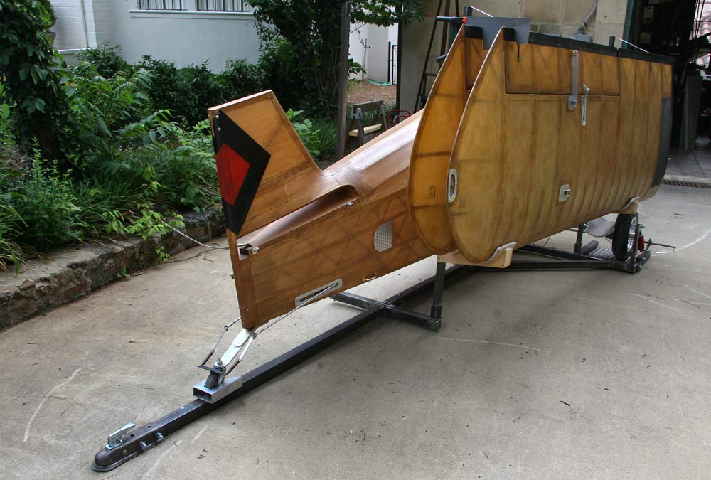
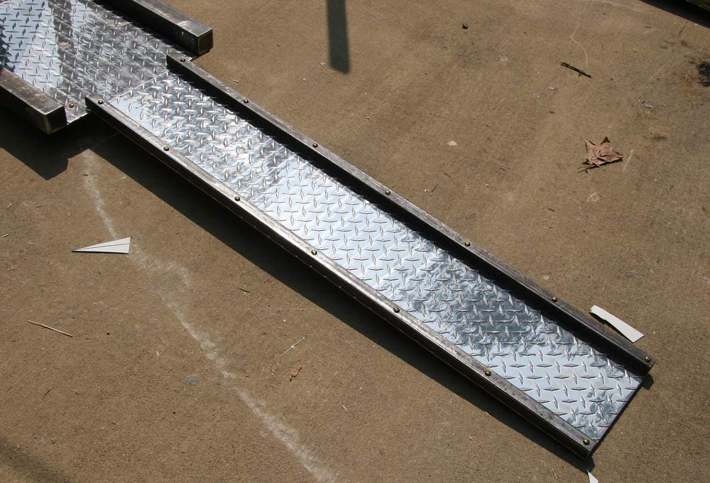
I made the two ramps to get the plane on the trailer using 2 pieces of 1" x 1" square steel tubing cut about 1" longer than the 10" x 48" pieces of aluminum tread plate , and attached on each side with 7 brass screws.
A friend raised some concern with the center of gravity of the loaded trailer and tongue weight I would end up with, so I propped up the axles and checked the tong weight unloaded at about 37 lbs. When I had the engine fitted on the fuselage earlier, it balanced roughly on the front attachment channel of the gear, and the center of gravity of the fuselage alone on the gear should be just slightly behind the wheels axle. With that assumption, I made the pads for the wheels on the trailer long enough so that the wheels of the plane could be lined up with the trailer axles, or slightly forward, or behind. The position of the tail wheel pad will later be adjusted forward or backward with the whole plane on the trailer so I get the proper weight on the ball. I can also raise the tail if necessary to move the center of gravity back, and play with the location of the loading ramps, but I believe I have enough leeway already as it is. When the correct position is determined, I will make blocks and spacers for the wheels.
The figures for tongue weight I got are of 10% to 15% of gross weight. Gross weight should be in the neighborhood of 800 lbs, so that would make it between 80 and 120 lbs.
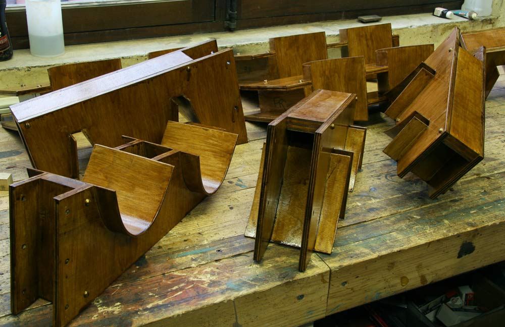
I ground and sanded the four plywood cradles and the four top stops , and gave them a coat of varnish.
| L A S T M O N T H | N E X T M O N T H | B A C K T O I N D E X |