|
| C
O N S T R U C T I O N L O G 18 |
|
| A P R I L 2 0 0 6 |
|
 |
|
| Spring seems to be here for good, the workshop is cleared, all the airplane parts have been moved up to it and stored. Lets get this thing finished and crank it up! |
|
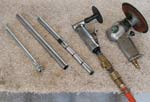 |
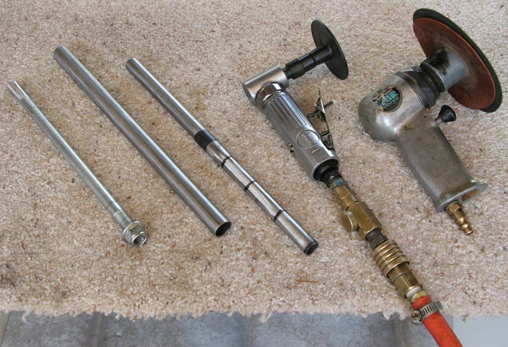
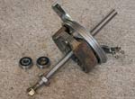
I received my pieces of steel tubing from Aircraft Spruce, and the bearings from JC Whitney , so I got to work on the axles. I sanded the 5/8" tube down to 15mm, working first with the big 5"disk sander, then with the 3"sander. I sanded only the length of tube that fits between the 2 bearings inside the hub. I drew 4 black marker lines around the tube between each pass to keep the sanding even. It actually took a good while to whittle down that 5/8" down to 15mm...
I cut the tube down to correct length and ground the head off the 12mm axle bolt so it fit tight inside the tube. The threaded end will be welded to the edge of the tube. to the edge of he threaded end will ht inside the tubeinside the . |
5hrs |
|
|
 |
 |
 |
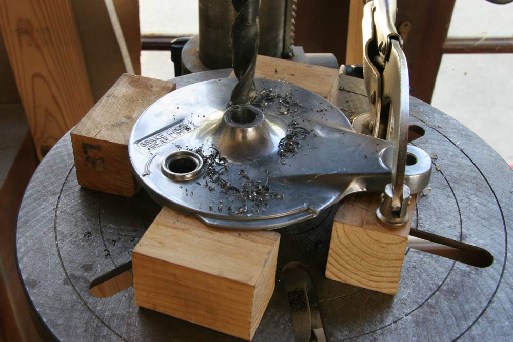
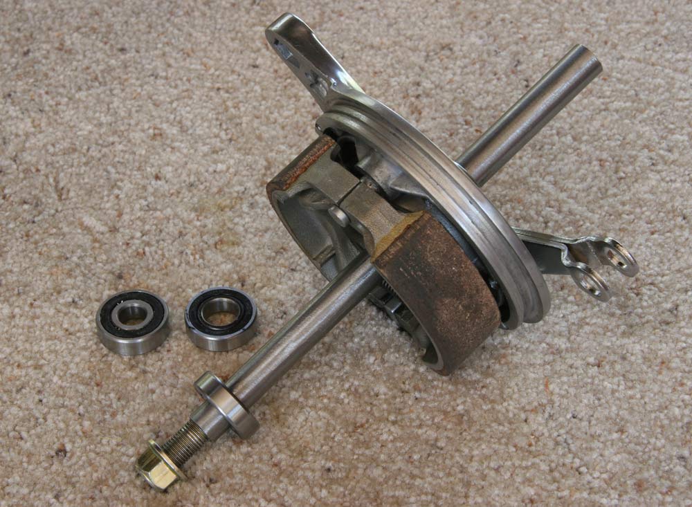
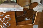
I drilled the bronze bushings of the drum brake units to a 5/8" bore and fitted everything. The axle assembly shown on the left will be welded to the 3/4" spacer tube and to the 7/8" axle tube so they fit tight against the drum brake unit. |
2hrs |
|
|
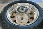 |
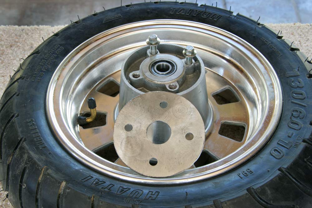
I removed the smaller 12mm bearings from the hubs and replaced them with the 15mm.
I cut two 1/8" aluminum disks and ground them to cover the open end of the hub. |
3hrs |
|
|
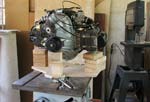 |
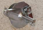
I made a support for the engine and got my yardman to help me load it up on a trolley and wheel it up to the workshop, where I sat it on the table saw base. I mounted the motor mount on with the Lord Mounts loose and adjusted the fit so there is no stress on the rubber , and the mount holes line up as perfectly as possible with the engine mounting holes. I will use spacers between the mount and the engine, and that will give me some lateral adjustment of the thrust line if needed... |
2hrs |
|
|
| I got my friends Mike and Gib to help me move the fuselage up the long outside steel staircase to the street level workshop for final assembly . I fits fine diagonally, and there is actually more space to move around it than I expected. It will get tighter with the engine and prop on though. |
|
 |
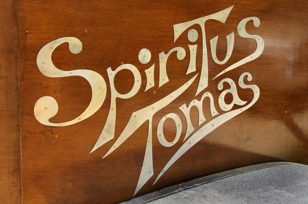
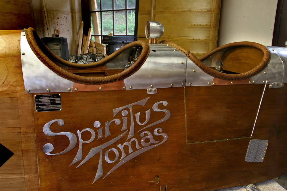
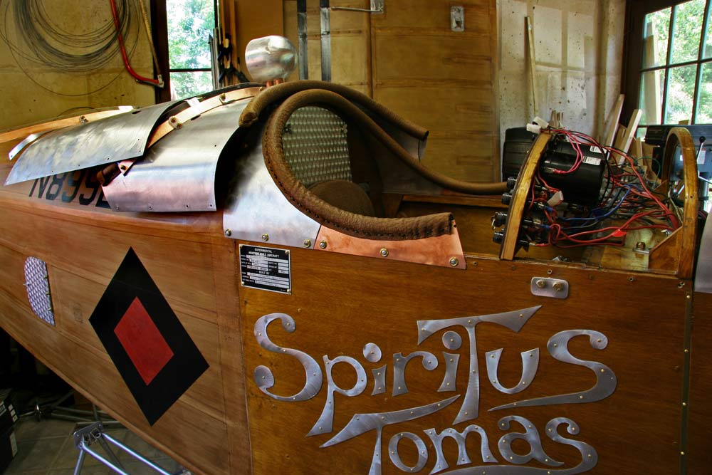
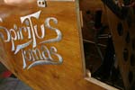
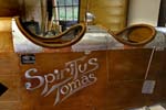
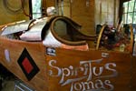
I finished attaching the letters of the name on the right side by the rear cockpit, leaving space for the front cockpit door I still have not made my mind up to cut ... |
2hrs |
|
|
 |
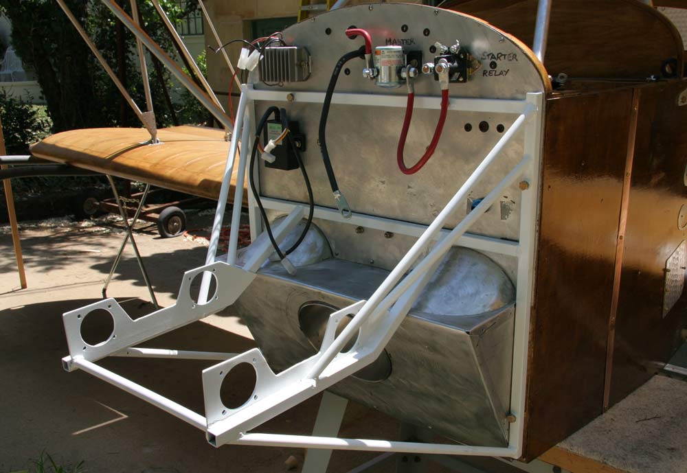
I took the motor mount to be sansblasted, and gave it multiple coats of white epoxy enamel. I found powdercoating expensive, and overkill for my purpose anyways. This plane is unlikely to get heavy duty service...
I installed it on the firewall with no problems at all, the holes lined up perfectly and the bolts went right in. The heat treatment did not cause any distorsions at all. |
2hrs |
|
|
|
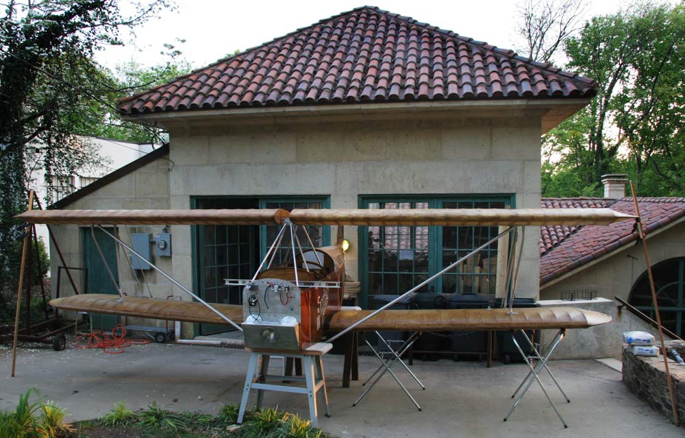
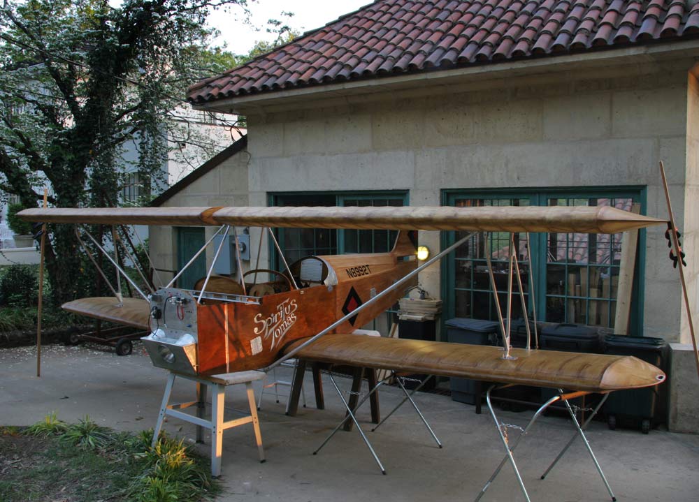
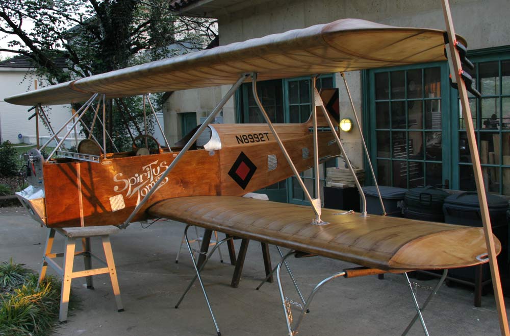
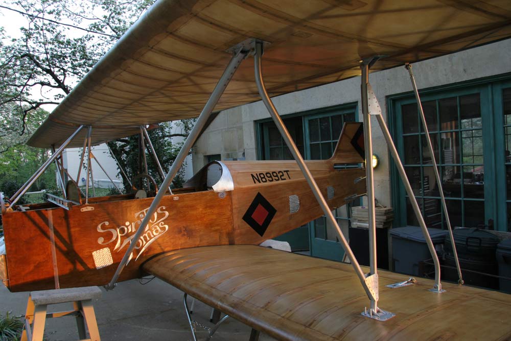
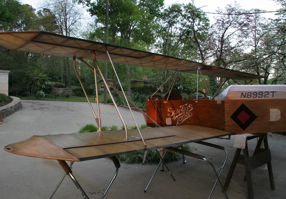
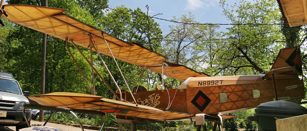
| The weather was so nice and supposed to stay nice a few more days through the Easter week end, so I took the plane out and assembled it in the driveway. I leveled the fuselage both ways, and attached the wings. I had not done that since before covering, and it was a whole adventure again. The fit was very tight, and I had to work at it, but it turned out so beautiful with the sun casting shadows of the internal structure on the skin . I started to make the landing wires. I had been debating whether to use the second strut or to replace it by a pair of flying wires like the Celebrity. That strut looks heavy and would get in the way when attaching the wings, so I am going to go with the wires. There is not much info supplied by Fisher on those. My blue prints are so confused they call the landing wires flying wires..., but then again, I am building a 1992 kit. I will call Gene tomorrow to verify the attachment points . |
|
| I called John Burgin, the EAA advisor who will also do the final inspection for the FAA to see if he might be able to stop by and take a look at it before the rain comes, and he stopped by this Easter afternon . He looked the plane over, and we went over some questions and small problems with the rigging, as well as plans with the engine installation. He pointed a couple loose places at the struts attachment points which I was aware of and already planning to fix. He told me where to place the ID Plate on the outside of the fuselage, and the EXPERIMENTAL sign in the front cockpit bare panel. He looked over the new landing gear and the engine mount. He gave me the list of the documents he would require for the FAA inspection. He finally offered to come back if I needed advice, and I appreciate that very much. It has been a little lonely since Dick Simpson gave up his Tiger Moth and passed away. Nobody else in the area is building a wooden airplane these days. |
|
 |
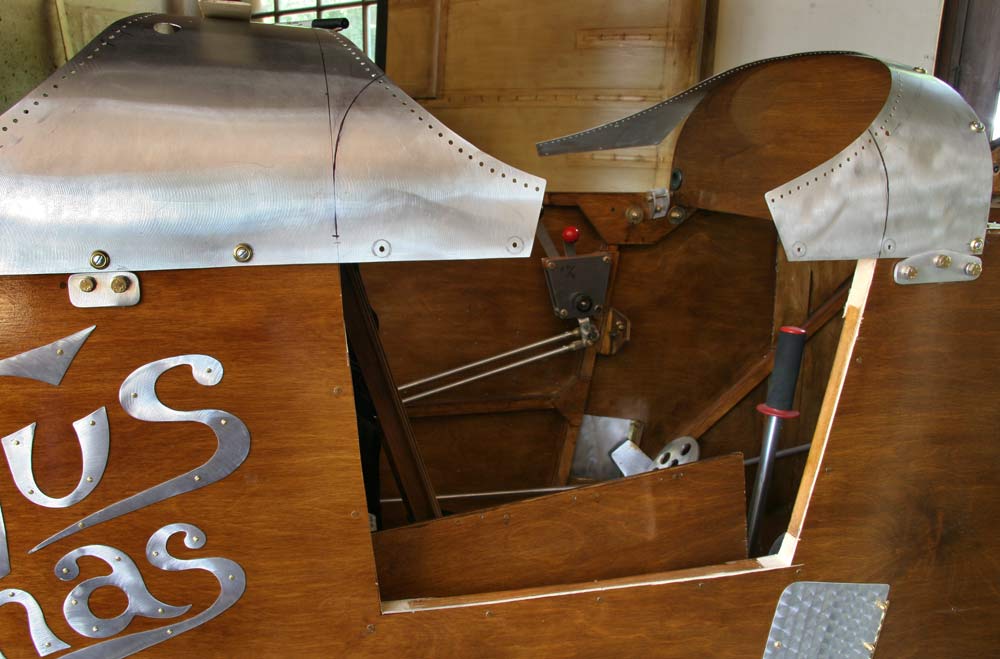
I finally bit the bullet today and cut out the access door to the front cockpit with my japanese hand saw. I don't know why I worried so much about it for so long, the fuselage is still as rigid as can be.
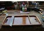
I attached the two curved top aluminum cowling pieces back on, after bending them so they fit the curve of the panel exactly without the screws on, so when the 2 small sections marked that will be part of the door are cut and attached to the top of the door, they line up with the rest of the cowling. |
2hrs |
|
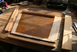 |
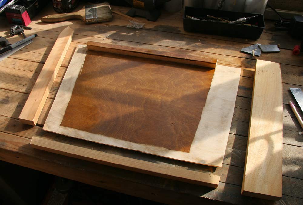
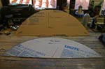
I cut part of the top longeron. I sanded the varnish off the inside of the door panel so I can glue the frame, and cut the 3 pieces to frame it. The bottom piece is 7/8" square left over longeron material , the front section is 7/8" x 1 1/2", and the back section 7/8" x 3". These two extend above the top longeron. The reason for that is so I can stiffen the small curved aluminum parts of the door by gluing them to those front and back sections. |
1hr |
|
 |
I clamped the door frame sections into the opening and marked the 1/8" plywood panel in place to get a tight fit. |
1hr |
|
 |
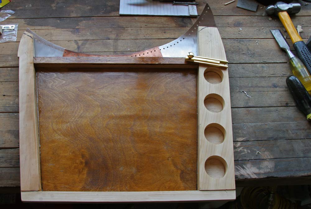
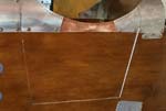
Three holes were cut out of the 3" wide section. The front and back sections were cut to fit the curve of the cowling, and the 3 sections were glued together and to the 1/8" panel I cut out.
A section of aluminum hinge was cut , fitted to the front of the door, and attached with brass screws. |
2hrs |
|
 |
Two wooden stops were glued to the door frame.
|
1hr |
|
 |
The door was installed and a sliding brass bolt attached. |
1hr |
|
 |
The 2 small aluminum door pieces were cut off the rest of the cowling, and fitted to the top of the door. |
2hrs |
|
 |
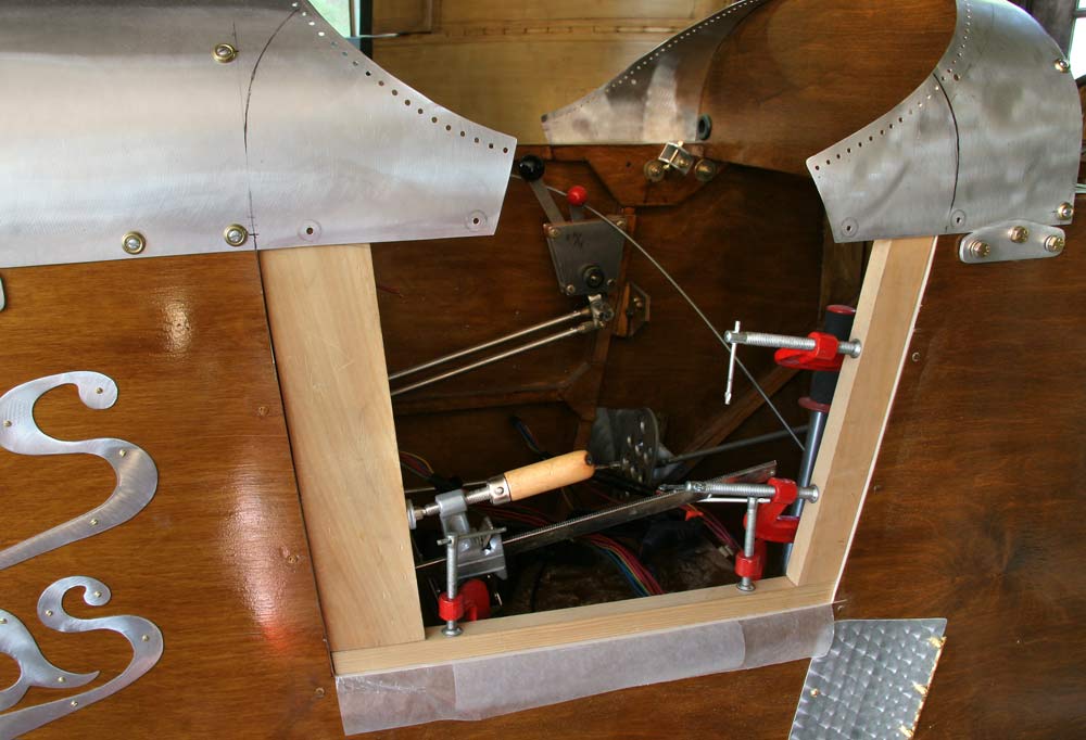
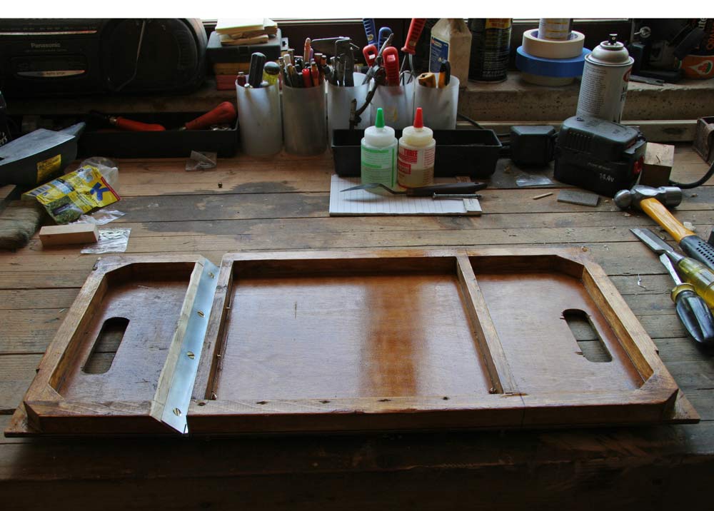
The pilot seat could not be taken out or dropped in easily without disconnecting one of the aluminum rudder tubes and sliding it back out of the way, so I decided to break it into 2 hinged sections. As it turns out, it still won't go in, so I will hinge the other side as well. |
2hrs |
|
| |
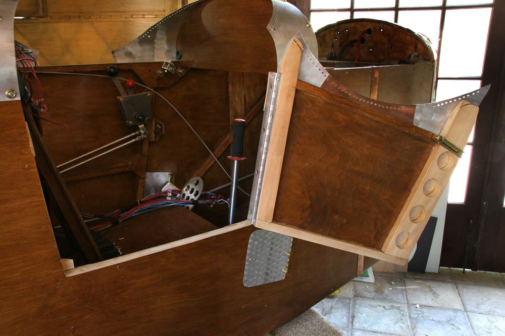
The other side of the seat was cut and hinged too. The seat can now be removed without interference fron the rudder push/pull tubes. |
2hrs |
|
|
 |
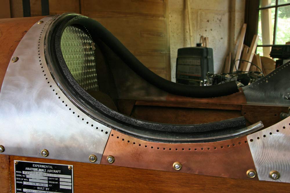
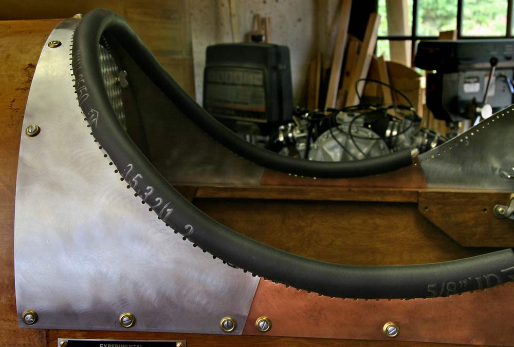
I got some high grade 1/2" thick black rubber pipe insulation from Lowes and trimmed it in width so it just wraps around a 1/4" ID clear vinyl tubing, glued the side with peel off adhesive to the inside of the cockpit opening, and brushed contact cement on the inside, the external edge of the cockpit opening and the clear vinyl tubing. Placed the tubing on the edge. Its purpose is to fill the center and keep the thin aluminum turtledeck to cut through the rubber insulation when pressure is applied. |
2hrs |
|
 |
The insulation is wrapped around and glued to the outside of the cockpit opening, leaving the holes just barely exposed. |
1hrs |
|
 |
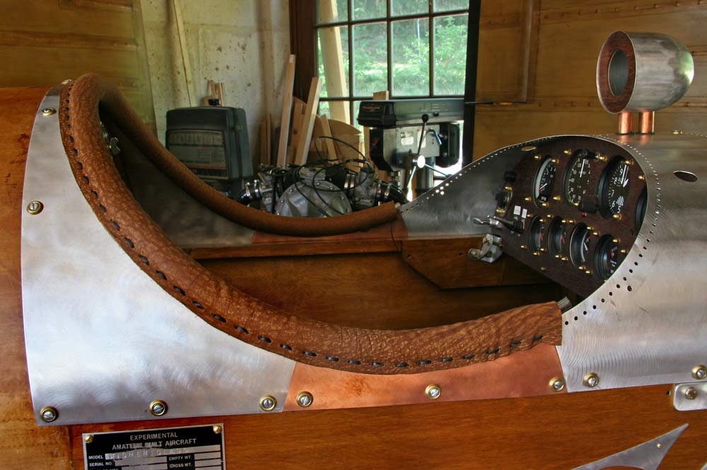
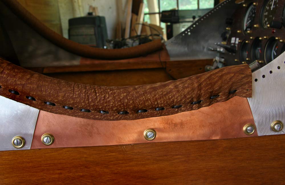
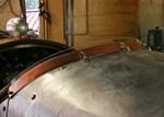
I cut a 3 1/2" wide leather strip( I had determined by trying a short section that this was the correct width to get it tight), punched a row of holes on each side to match the holes in the aluminum turtledeck, and laced it on with small flat brown leather lacing cord from Tandy Leather and a special fat screw on brass needle. |
3hrs |
|
 |
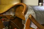
This is a close up of the finished padded collar. I left breaks in the padding so the panel section of the turtledeck can be removed separately. |
2hrs |
|
 |
I cut more leather strips, punched them, and laced them around the rest of the cockpit openings. Looks real good! |
8hrs |
|
 |
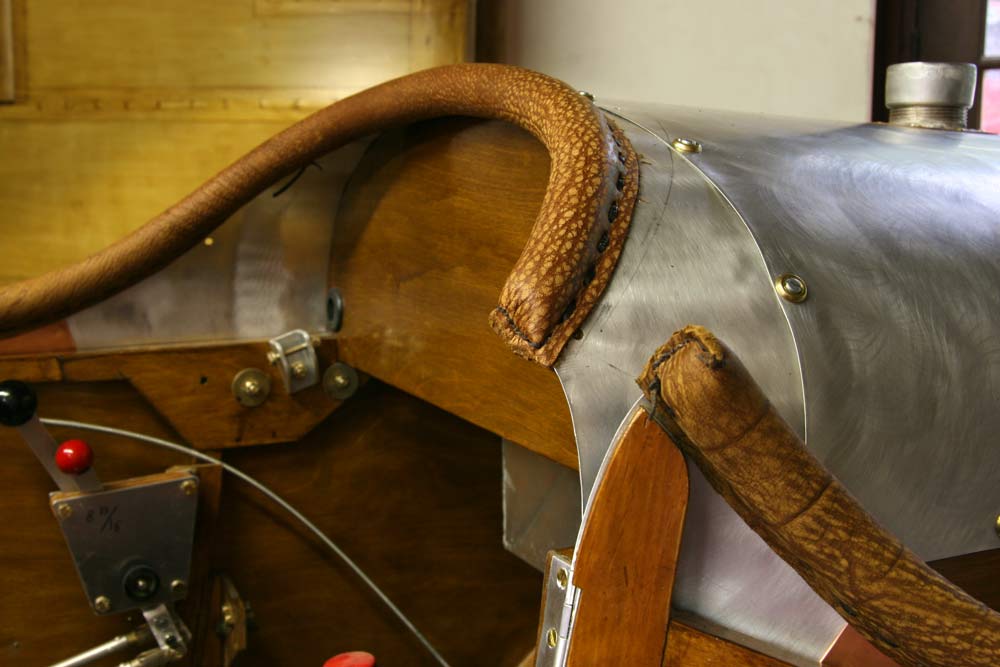
The door required a little fitting, and stitching the ends closed with a slant so it closes over the sides. |
1hrs |
|
|
 |
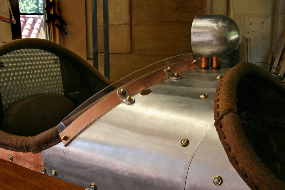
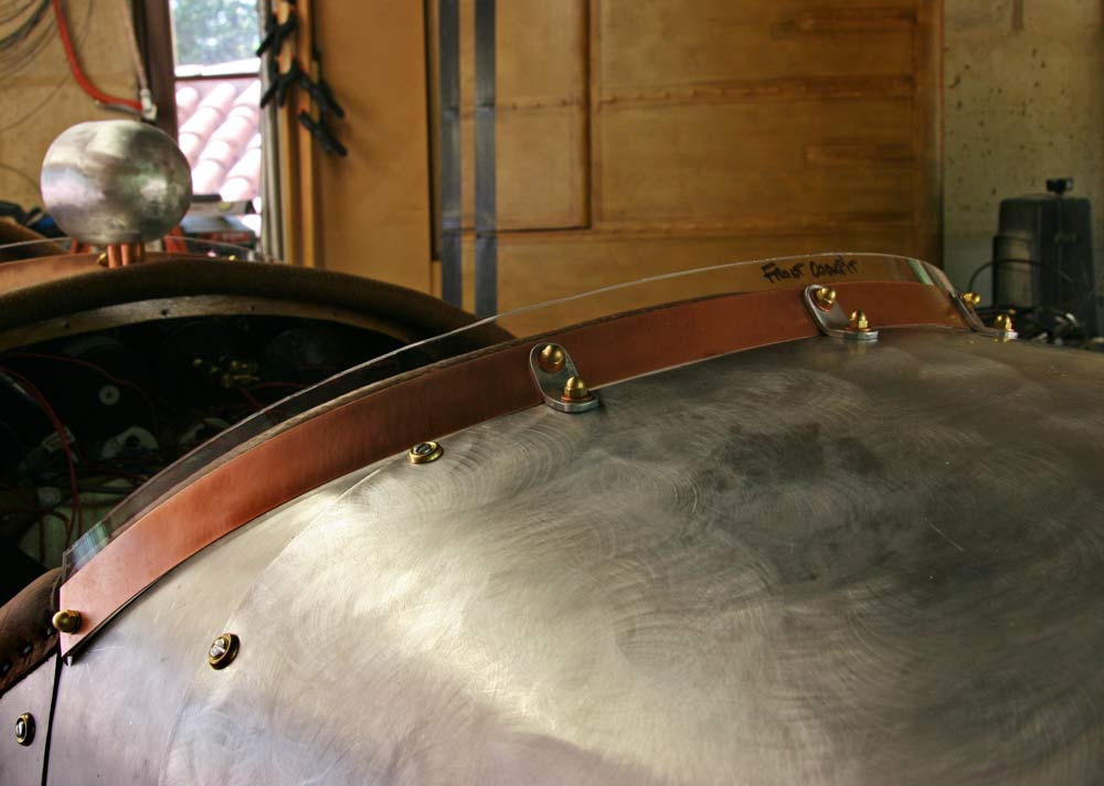
I modified and improved the windshield mounts using a strip of plexiglas between the aluminum and the copper strip, and making larger brackets attached to the front to replace the small ones I originally had on the back side(it was too hard to get to the screws). I had to epoxy 2 pieces of brass threaded rod into the top of the panel. |
4hrs |
|
 |
The front windshield was done the same way .
I cut new plexiglas windshields and drilled holes matching those on the strips |
3hrs |
|
 |
I removed the turtledeck panels and reconnected the panel wiring.
I ordered 10ft extension leads for the CHT sensors. |
2hrs |
|
 |
I cut new windshield panels and drilled them to match the plexiglas strips. |
2hrs |
|
| |
|
| TOTAL 1251hrs |
|
|