 |
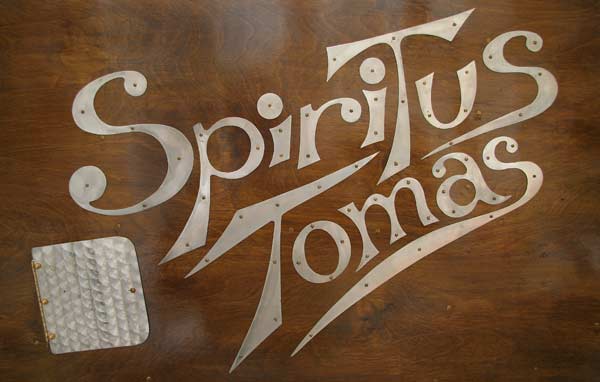
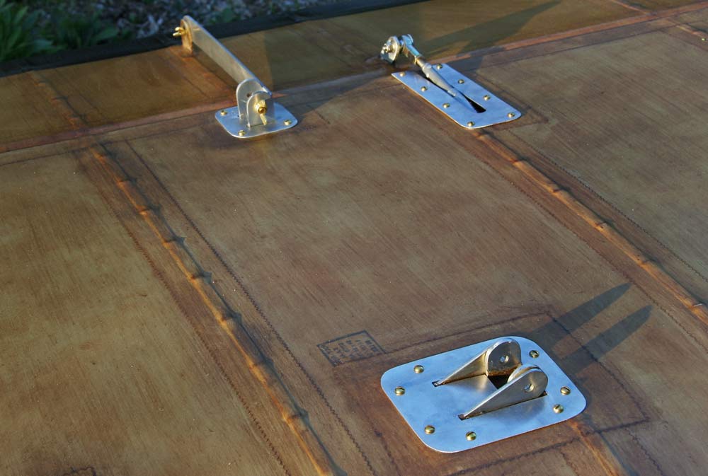
I attached the cutout aluminum letters of the name Spiritus Tomas to the left side of the fuselage with the smallest brass screws I could find. I may have to glue them down eventually, as I stabbed the shit out of my finger just lovingly running my hand over them...
|
2hrs |
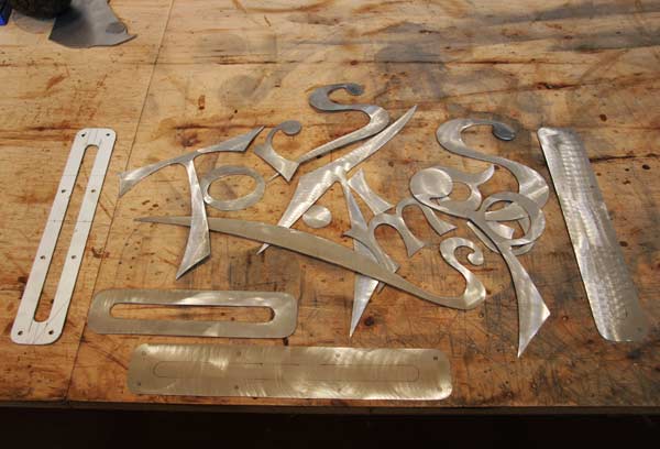 |
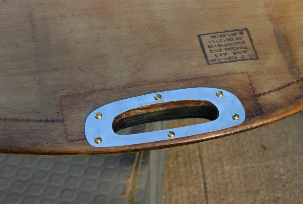
I cut out and ground smooth the letters for the other side, as well as 3 trim pieces for the rudder and elevator control rod slots.
|
6hrs |
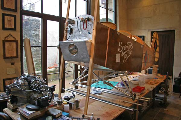 |
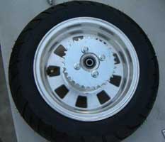
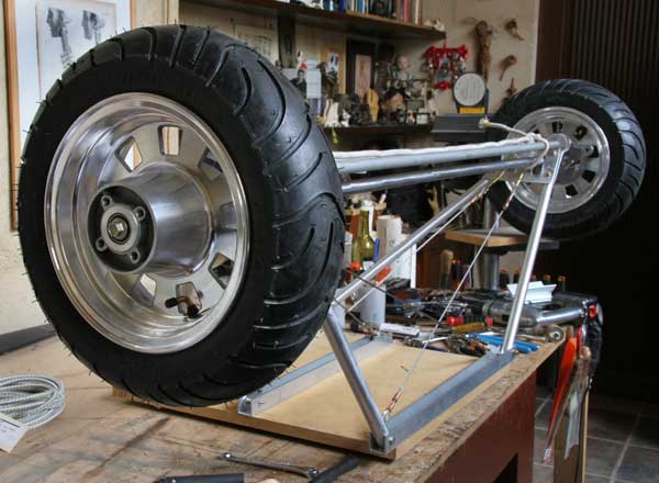
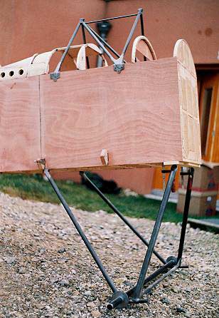
I raised the fuselage up on stilts and attached the old geat to design and make the new WW1 type straight axle gear I have been thinking about for months. At 36 lbs each, the Harley wheels and tires are just too heavy, I will use them on the trailer I am planning to build for the plane. |
1 hrs |
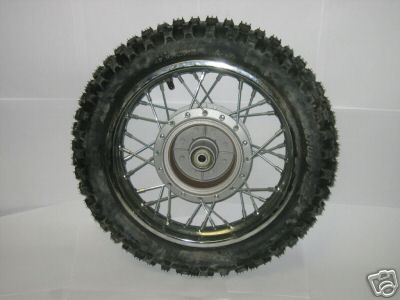 |
I went looking on e-bay again, and found some 12" pit bike rims that looked like they might be a good option, so I ordered them. |
2hrs |
 |
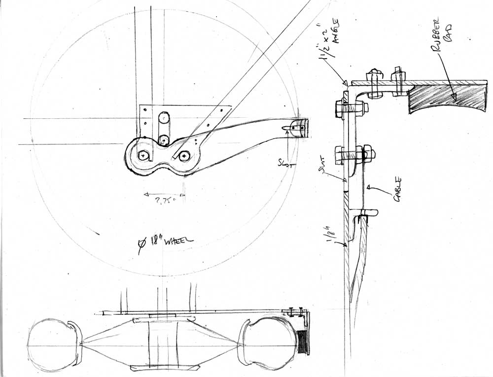
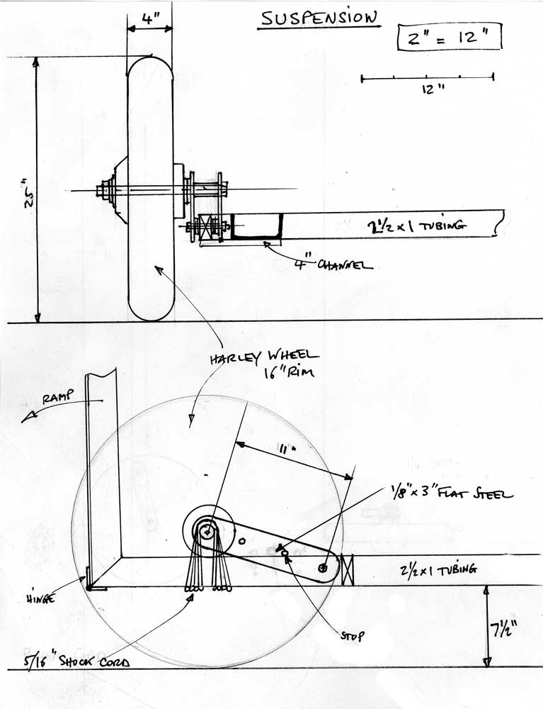
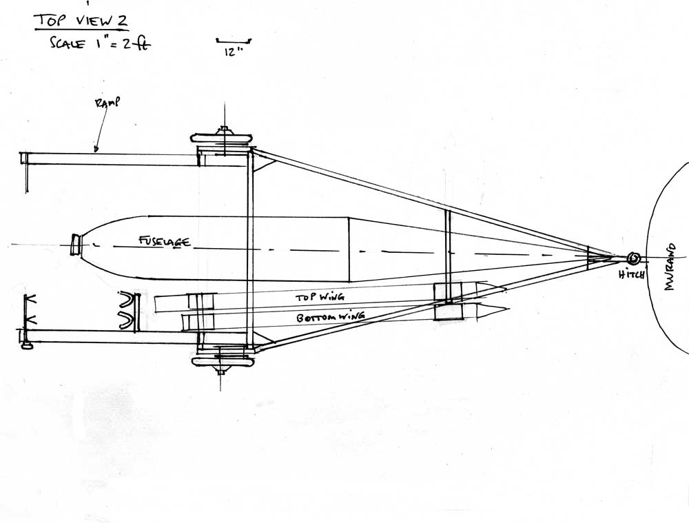
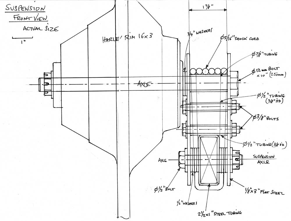
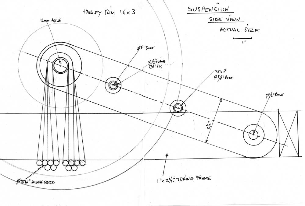
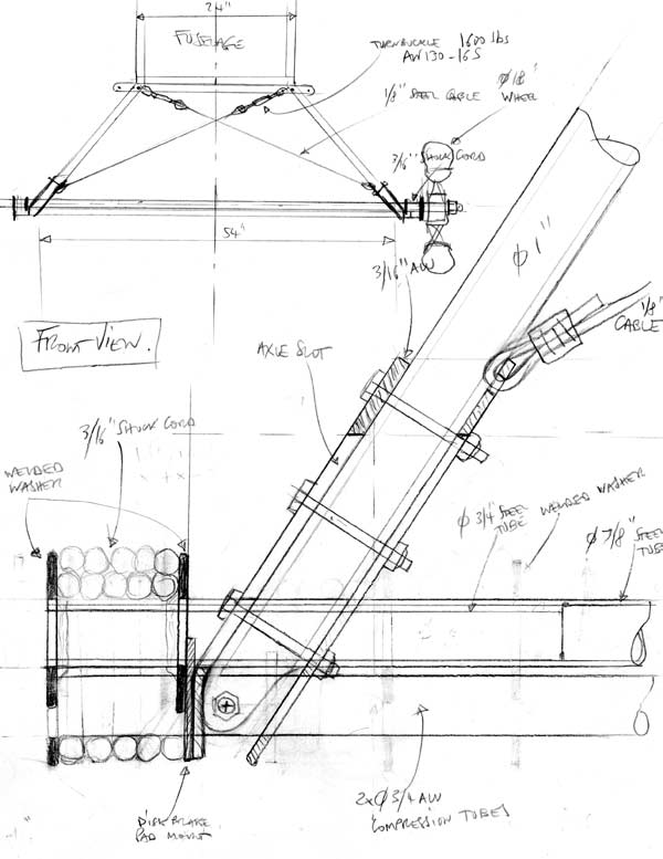
Now for the new landing gear design. I have a great book of blueprints of a number of WW1 planes published by the Model Airplane News, and some have pretty detailed drawings of the landing gear. In particular, the Albatros, the Fokker, the Pfalz DIII and PFALZ DXII . I also went back though pictures I had collected of the Pietenpol, Flitzer and other landing gears. There are basically 2 ways to run the shock cords: around tubes parallel to to the axle, or around stubs perpendicular to the axle. I decided to go with the former and did some preliminary sketches in front view and side view. I want to make the new gear a little higher with a straight back leg (the back leg of the existing gear is bent), which means the attachment point to the fuselage has to be moved back to the rear spar carry thru. It also has to be moved in towards the center of the fuselage so as not to interfere with the bottom of the wings. I designed a bracket that would bolt to both the spar carry thru and the bottom longeron . | 3hrs |
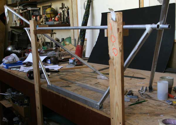 |
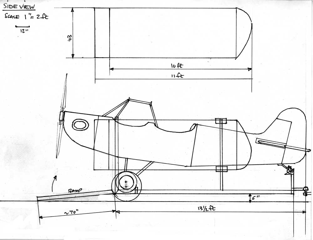
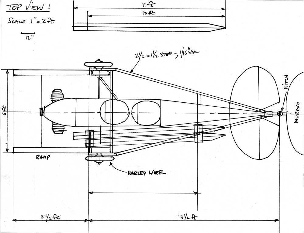
I built an upside down jig on my bench to hold the two 3/4"and 1/16" wall aluminum ties in place 18.5 " above the table top, while I cut and fit the legs. That would place the axle 17.5" below the bottom of the fuselage, instead of the 15" of the present configuration. The wheels that came with the plane are 14"OD, so assuming the 12" wheels I orderd are about 18"OD with the tires, that would raise the fuselage a total of 4.5 ". Gene says 3" is no problem. That means I may have to raise the tail wheel a couple of inches. | 2hrs |
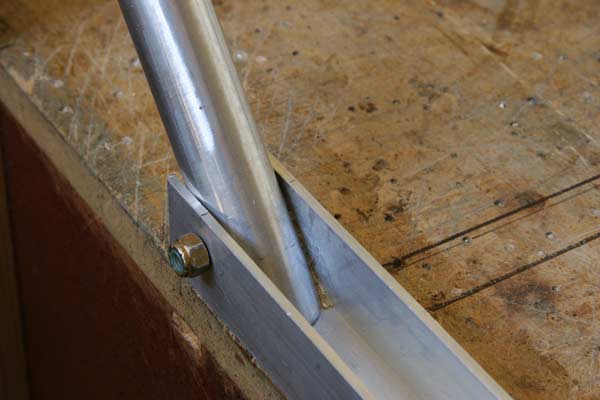 |
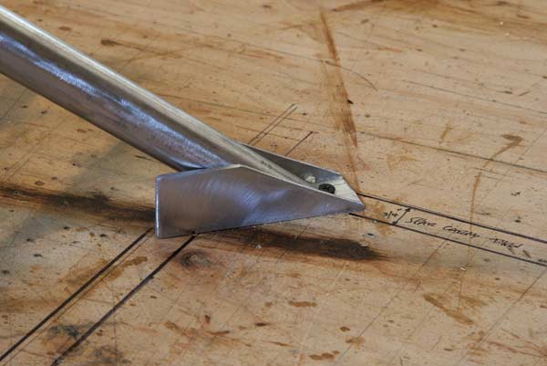
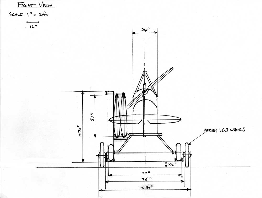
The front legs on the existing gear are at a 50 degree angle to the bottom of the fuselage. The question is do I keep the legs on the new gear the same . Most WW1 planes had fairly vertical legs and a narrow stance. I am well aware that there would be less stress on the holding cables if the legs were more vertical, but on the other hand the wide stance should make the plane more stable on the ground. I like that... The front leg pieces were cut (out of 1" aluminum tubing with a 1/8" thick wall) at that angle and bolted so the beveled end fits tight against the channel. |
2hrs |
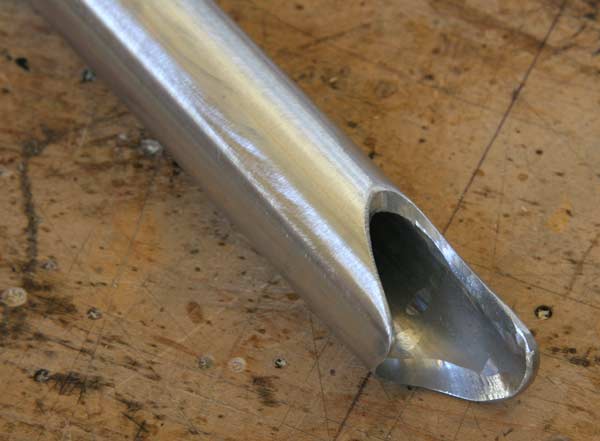 |
The other end of the front legs has to be ground and fitted by trial and error to fit against the 3/4" aluminum cross tie as perfectly as possible, with a tab on one side to bolt them to the cross ties. | 2hrs |
 |
The back leg is cut to approximate length and tentatively put in place to determine the angle of the attachment of the bracket to the bottom of the fuselage , its exact shape, and the position of the attachment bolts. | 1hr |
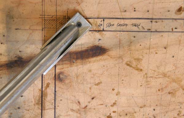 |
The wing drops slightly below the bottom of the fuselage at the front spar, so the bracket cannot stick out from the side of the fuselage , and is cut on a bevel. It will be bolted to the side longeron and to the front spar carry thru. | 1hr |
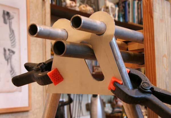 |
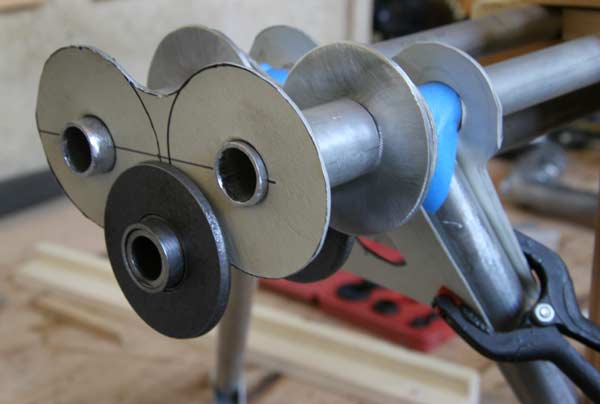
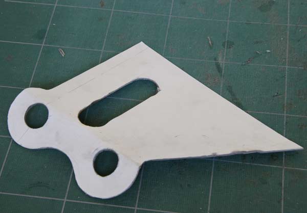
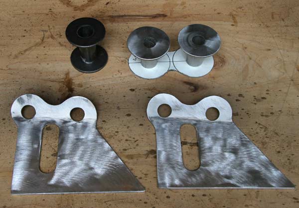
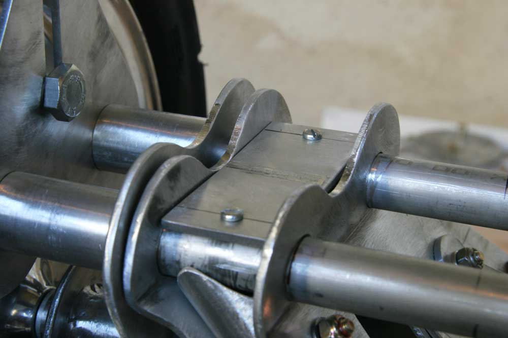
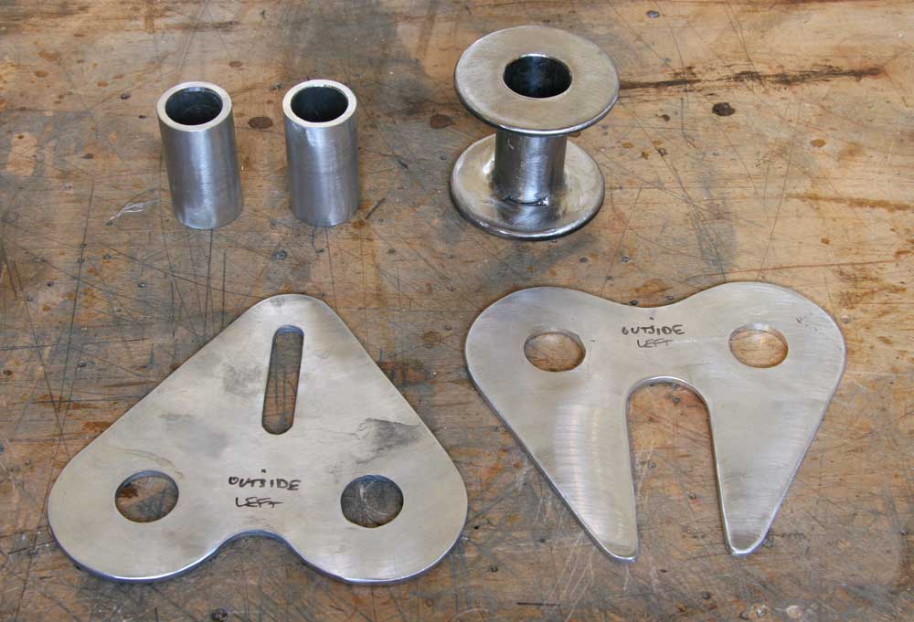
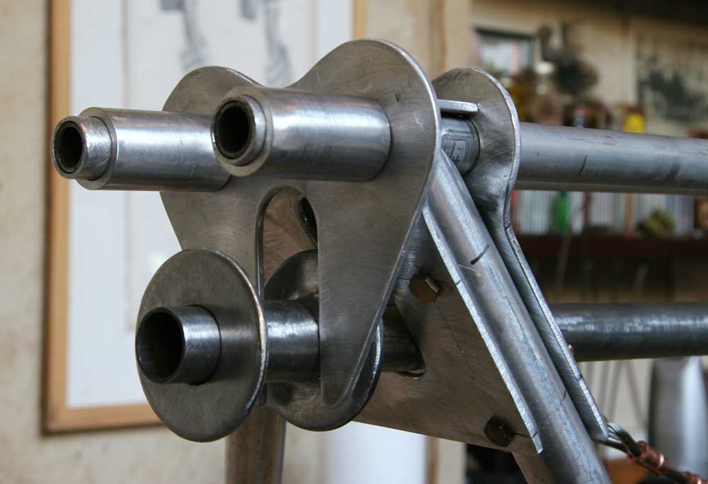
There is no way to draw on paper the exact shape of the 1/8" aluminum plates tying the legs together , so I just cut a cardboard template and fitted it . See the guiding slot where the axle will move up and down as the shock cord is stretched on rough landings. | 2hr |
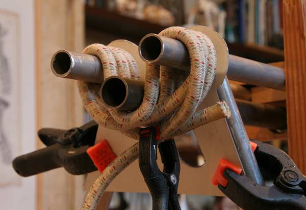 |
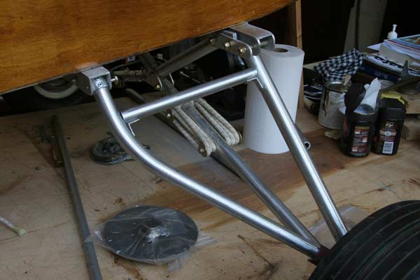
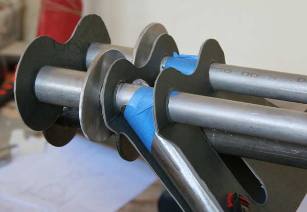
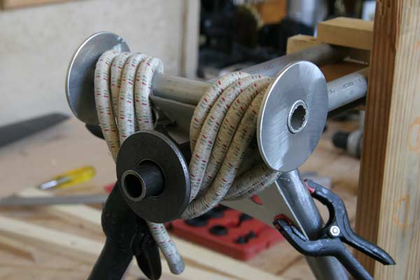
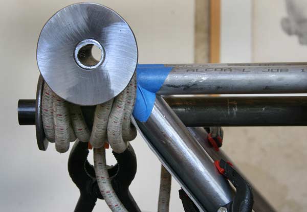
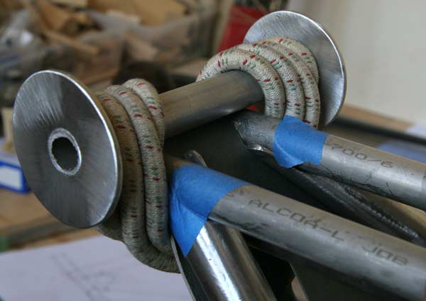
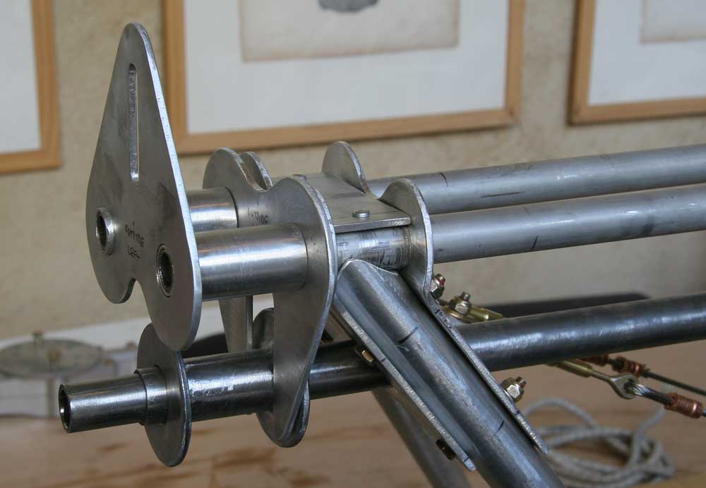
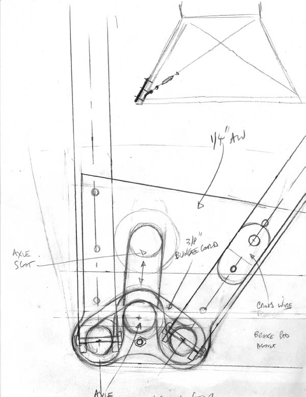
This image shows the way the shock cord will run around the 2 ties and the axle. There will be large aluminum washers on the two ties, and steel washers welded to a short tube fitting over the axle to keep the cord from moving laterally. I cut them.The images below show the arrrangement. | 2hr |
 |
 |
 |
 |
 |
 |
The outside aluminum washerscould be joined , and even extended out and used to mount a pad brake to the exterior of the tire. | 3hr |
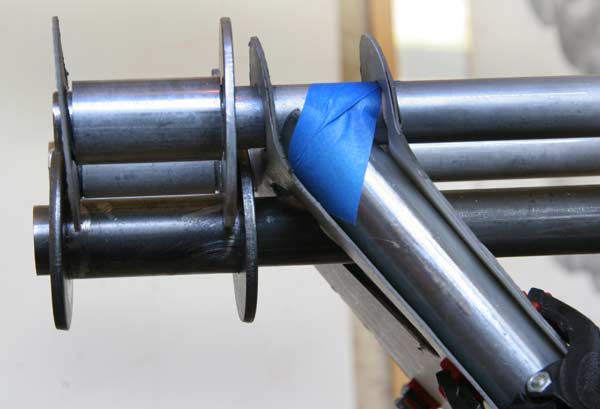
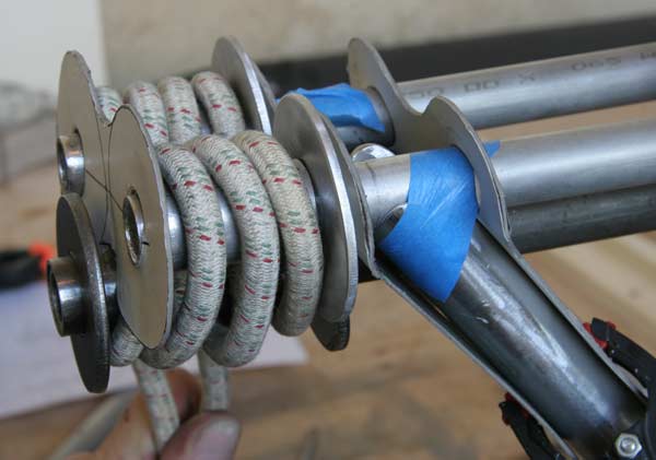
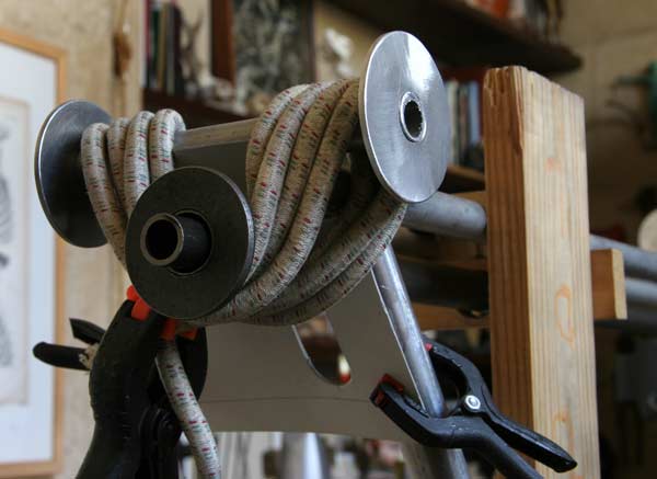
Just to see, I put together a mock up of the other possible configuration for the shock cord. See pictures below. I don't like the fact that the shock cord rubs against the edge of the plates holding the legs together, and also that it drops substancially below the axle.
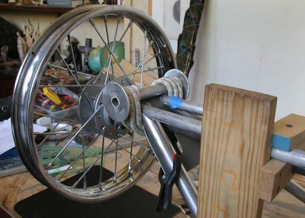
The spoke wheels came today from e-bay, and they are just rims with no tires as was shown in the picture. One has to read the small print... Also, they are the wrong size, 16" rims instead of 12" . And the hubs are only 3 to 4 inches wide, which is not enough. I called the seller, and got a very unfriendly person that would not listen to me and just told me to go to their site and follow the return procedure, which means I would have to pay for shipping the rims back. I don't think the 12" rims would be strong enough either. I might just keep them, order 2 more, and make a toy Bugatti...
 |
 |
 |
 |
 |
3hr |
 |
I went to a couple of motorcycle shops to look at pit bike wheels, and saw some really nice and sturdy Kawasaki rear wheels with really wide 6" or 7" hubs. The problem is that they cost a fortune, something like $750 each! So I went back on e-bay and looked some more, and ran across these 10 " wheels with built in drum brakes and wide low tread street tires included. I e-mailed the seller, and the hubs are about 5", the axles 12 mm. I ended up ordering them, and am awaiting their arrival with my fingers crossed. |
 |
 |
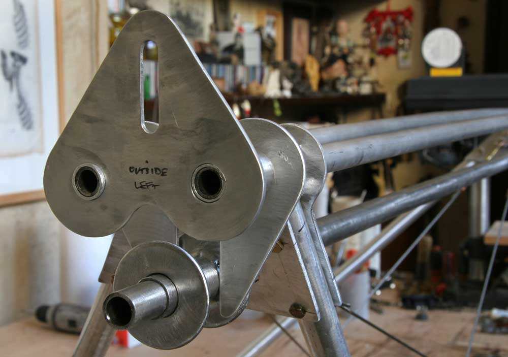
I cut the two plates out of 1/8" aluminum and bent them to fit | 4hr |
 |
I then fitted the legs on the other side to match, and made those plates too. | 2hr |
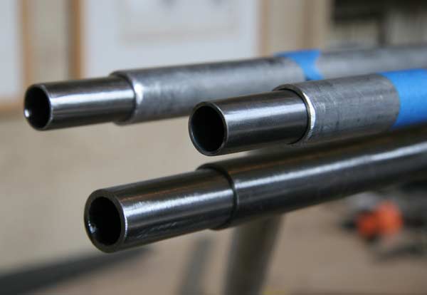 |
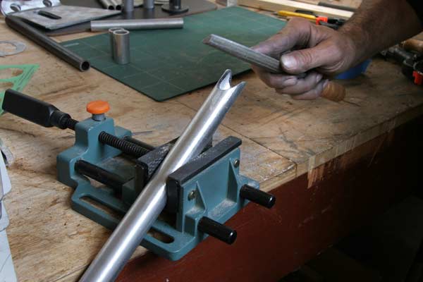
The two aluminum tubes will be re-enforced with 5" steel tubing inserts, and the axle tube with 11" steel tubing into which the axle will fit. I had to dand the insert to fit tigtly in the axle tube. | 2hr |
I started to think about moving the plane to the upstairs workshop so I can put it together at street level , and wondering how to fit it in there since the doors open in instead of out and the space is barely big enough. I could hinge the doors the other way...
I also started to think about transporting it, and making a trailer that might be used to store it in the driveway instead of renting a hangar. It would have to be a huge trailer actually, about 8 ft wide, 8 ft tall and 18 ft long. So I did some google searches to see what was available, what parts cost, and what other people had done.
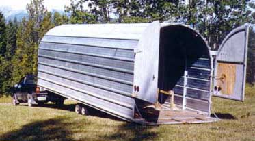 |
I did not find much on the last search, most people don't move their planes by car I suppose! Most of what I found was for gliders. One image shows how huge the trailer is and the idea of towing this thing scares me. I have towed some big U-HALL trailers and almost gone off the road. Of course,the plane is light, and a payload of 500 lbs or so is not much. Also, something that big is going to be pretty expensive. I found kits at http://www.utilitytrailerkit.com/ and http://www.championtrailers.com/UTILITY_TRAILER_KITS.HTM |
 |
 |
 |
2 hr |
|
8hr |
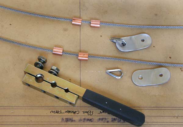 |
I made 2" brackets out of 1/8"x 1" aluminum bar(2024T3) to attach the cables to the chanel at the bottom of the plane , and the turnbuckles to the landing gear bottom plates, and fitted the cable ends with 2 copper Nicopress sleeves at each end. | 3hr |
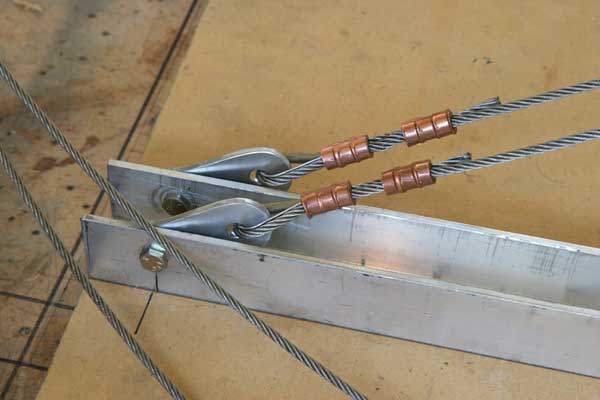 |
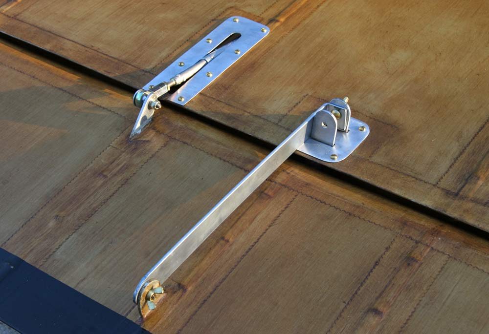
Here is a picture of the attachment to the rear chanel. | 1hr |
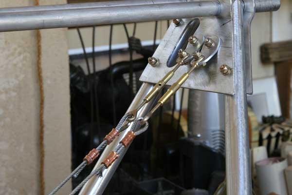 |
Here is a picture of the turnbuckles end . | 2hr |
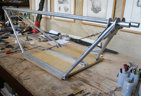 |
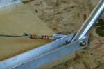
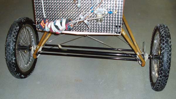
The cables touch where they cross in the middle, and I will make little leather protective sleeves to protect them. The gear is now bolted onto a 24" x 24" board , so it can be tested before it is mounted on the plane. Assuming the plane with the pilot is 700lbs, and a 3Gs bad landing, that would be a 2100lbs force. I plan to test the gear by loading 2000lbs or so on that board with the gear upright and the wheels on the ground. |
2hr |
 |
I moved the attachment point of the 2 front cables from the middle channel to the front channel , as close to the opposite leg as possible, which didn't even require making new cables. That way, on landing, the pull on that cable from one leg will be balanced by the push on the other leg. |
2hr |
 |
To stabilize the legs laterally before putting tension on the cables, I cut two 1/8" plates to fit tight between the two leg attachment plates on the bottom, and attached them to the compression tubes with small screws, after slipping inside the steel tube re-enforcements, drilling them and tapping them 6-32. |
2hr |
 |
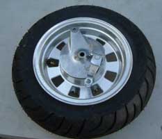
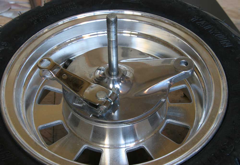
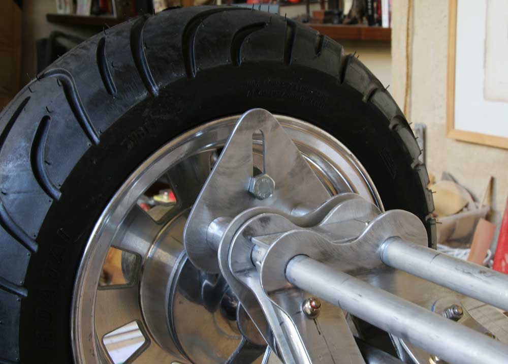
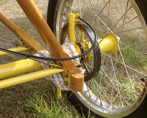
The mini-chopper wheels arrived today, and they look real good and sturdy. The hubs are about 6" wide actually. The axle bolts are 11". They weight 16lbs each. I moved the attachment point of the 2 front cables from the middle channel to the front channel , as close to the opposite leg as possible, which didn't even require making new cables. That way, the pull on that cable will be balanced by the push on the leg. |
2hr |
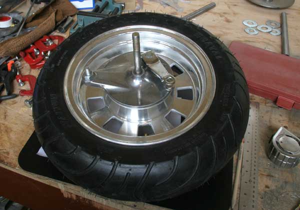 |
The only possible problem I see is the rather small 12mm axle size. I am considering changing the bearings to a larger size. Those on the wheel now are metric deep groove 6201-RS(32mm OD, 12mm ID, 10mm W). I searched the Internet, and the only 2 options with the same OD are a 6201-ZZ13( 13mm ID) and a 6002-RS(15mm ID). The problem is that 13 and 15mm are very very odd sizes, and axles in those sizes are almost impossible to find , as are 15 mm drill bits I would need to enlarge the bushing ID on the brake unit. Also , these bearings are pretty expensive. So I considered enlarging the bore of the hub to fit much more common and much cheaper 99502H-2RS bearings, which have an OD of 1 3/8' and an axle size of 5/8" . I took the wheels down to the machine shop, and was shocked that they wanted $150 per wheel to do it. Back to square one, the only solution is to use the 6002-RS bearings with a 15mm axle. I noticed that 15mm= 0.59055", and 19/32'= 0.5938", pretty close. But the only thing I could find in a 19/32' diameter is a drill rod, which is going to be too hard to thread or drill. Well, 5/8'=0.625". Could I not sand down a 5/8"OD tube (with a 12mmID) to a 15mm diameter. It is only hardly more than 1/32' to whittle down total, just 1/64" all the way round... I will use the 12mmm axle that came with the wheels inside that 5/8" OD tube. Now, I need to fit this 5/8" OD tube into my 7/8"OD axle tube. That will require another tube with a 5/8"ID and a 3/4"OD that will fit into the 7/8" axle tube I already have. OK I ordered the tubes from AS. |
5hr |
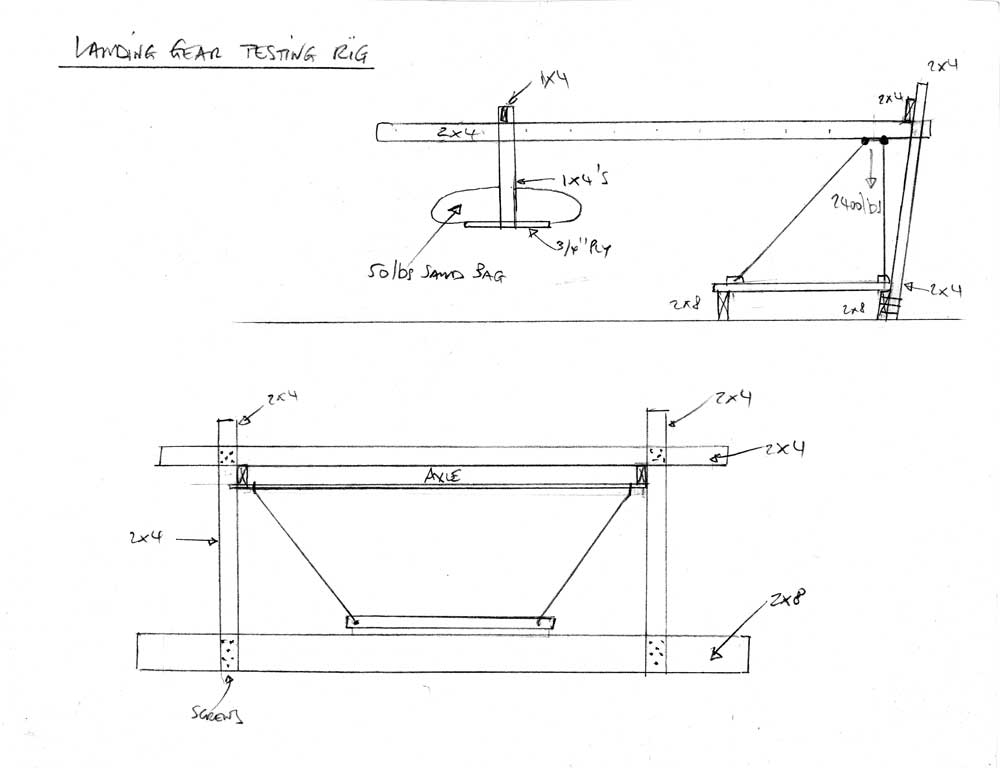 |
This is a sketch of the testing rig I plan to build to subject the gear to about 2000lbs. It is mostly 2x4's, and the pieces are assembled with sheetrock screws . It works like a scale, with two 50lbs sand bags as weights that can be moved down the lever arm to increase the force. |
2hr |
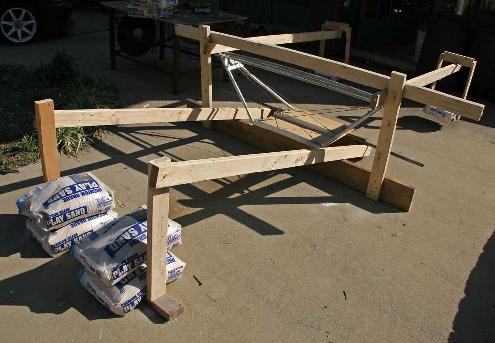 |
I built the rig as drawn, but had to add a 200lbs counterweight (4 sand bags) to keep the gear from tilting. |
5hr |
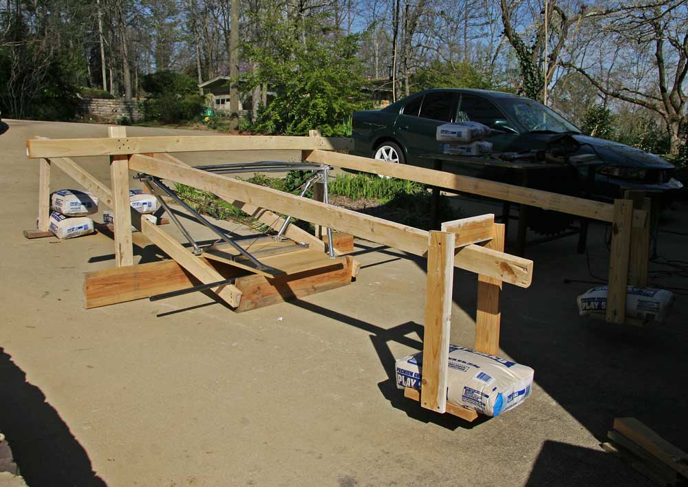 |
I moved the 50lbs weights slowly down the 8 foot 2x4's , until the total force was about 1700 lbs. |
2hr |
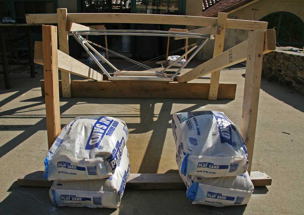 |
The axle tubing was noticeably bent up, as well as the two aluminum compression tubes, about 1 inch in the middle. I suppose that just adds to the spring. I would like to increase the force using 2 sand bags on each lever arm, and possibly test each side with 2000lbs, to simulate a 3 Gs landing on one wheel. |
2hr |
 |
 |
|
 |
 |
 |
 |
 |
 |
|
8hr |
I decided to finish up the wings before I take the fuselage up. I installed the aluminum plates around the attachment brackets and on the wing tips with short 3/8" brass wood screws. I touched up some of the oil paint antiquing.
I made special brackets attached with brass screws and wing nuts to hold the ailerons in place while the wings are moved.
| L A S T M O N T H | N E X T M O N T H | B A C K T O I N D E X |